Infrared light reflector

a technology of infrared light and reflector, which is applied in the direction of instruments, polarising elements, lighting and heating apparatus, etc., can solve problems such as coating failure, and achieve the effect of enhancing film strength

Active Publication Date: 2012-03-01
FUJIFILM CORP
View PDF1 Cites 16 Cited by
  • Summary
  • Abstract
  • Description
  • Claims
  • Application Information

AI Technical Summary

Benefits of technology

[0045]Heretofore, the polymerizable compound of the type was added to a light reflective layer containing a cholesteric liquid crystal compound for the purpose of enhancing the film strength, as described in Patent References 2 and 3. Therefore, in case where the layer contains the fluorine-containing alignment controlling agent in an amount of 60 ppm or more relative to the liquid crystal compound therein, the fact that the effect of the invention could be attained when a polyfunctional polymerizable compound is added to the layer is an unexpected and surprising result.
[0046]The infrared light reflector of the invention is described in detail hereinunder in point of the configuration, the properties, the materials, the production method, the use and others thereof.
[0047]With reference to the drawing attached hereto, one preferred embodiment of the infrared light reflector of the invention is described below.
[0048]The infrared light reflector 1 shown in FIG. 1 preferably has infrared light reflective layers (liquid crystal compound layer, CL layer) 12 on at least one side of the resin substrate 11.
[0049]Preferably, in the infrared light reflector 1 of the invention, the infrared light reflective layers 12 include infrared light reflective layers with a cholesteric liquid crystal phase fixed therein (hereinafter these may be referred to as cholesteric liquid crystal layers) 14a and 14b. However, in the invention, the order in lamination of the light reflective layers 14a and 14b from the resin substrate 11 and the number of the laminated layers are not limited to the order and the number illustrated in FIG. 1.
[0050]Preferably, the infrared light reflective layers 12 are in the form of a laminate of from 2 to 12 layers each with a cholesteric liquid crystal phase fixed therein as mentioned above.

Problems solved by technology

Given the situation, the present inventors tried producing an infrared light reflector having a laminate configuration of cholesteric liquid crystal layers by coating with a coating liquid prepared by adding a fluorine-containing alignment controlling agent to a cholesteric liquid crystal compound, but have found that, in coating with the next layer on the layer that contains a fluorine-containing alignment controlling agent, there occurs a problem of cissing failure in coating.

Method used


Image

  • Infrared light reflector
  • Infrared light reflector
  • Infrared light reflector

Examples


example 1

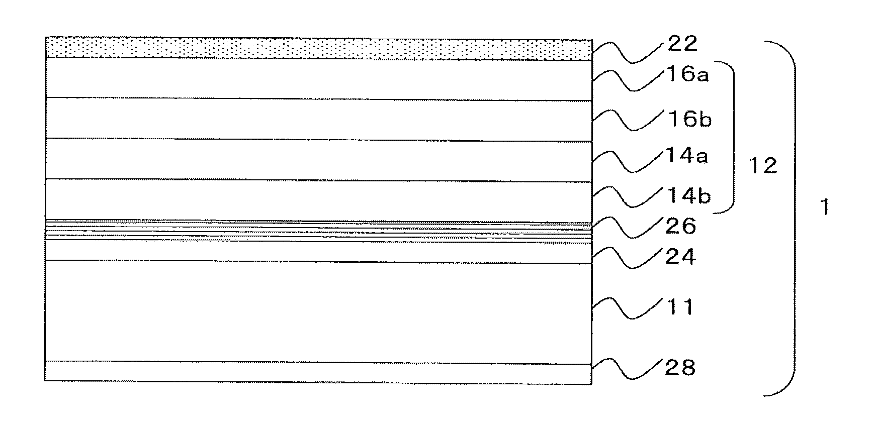
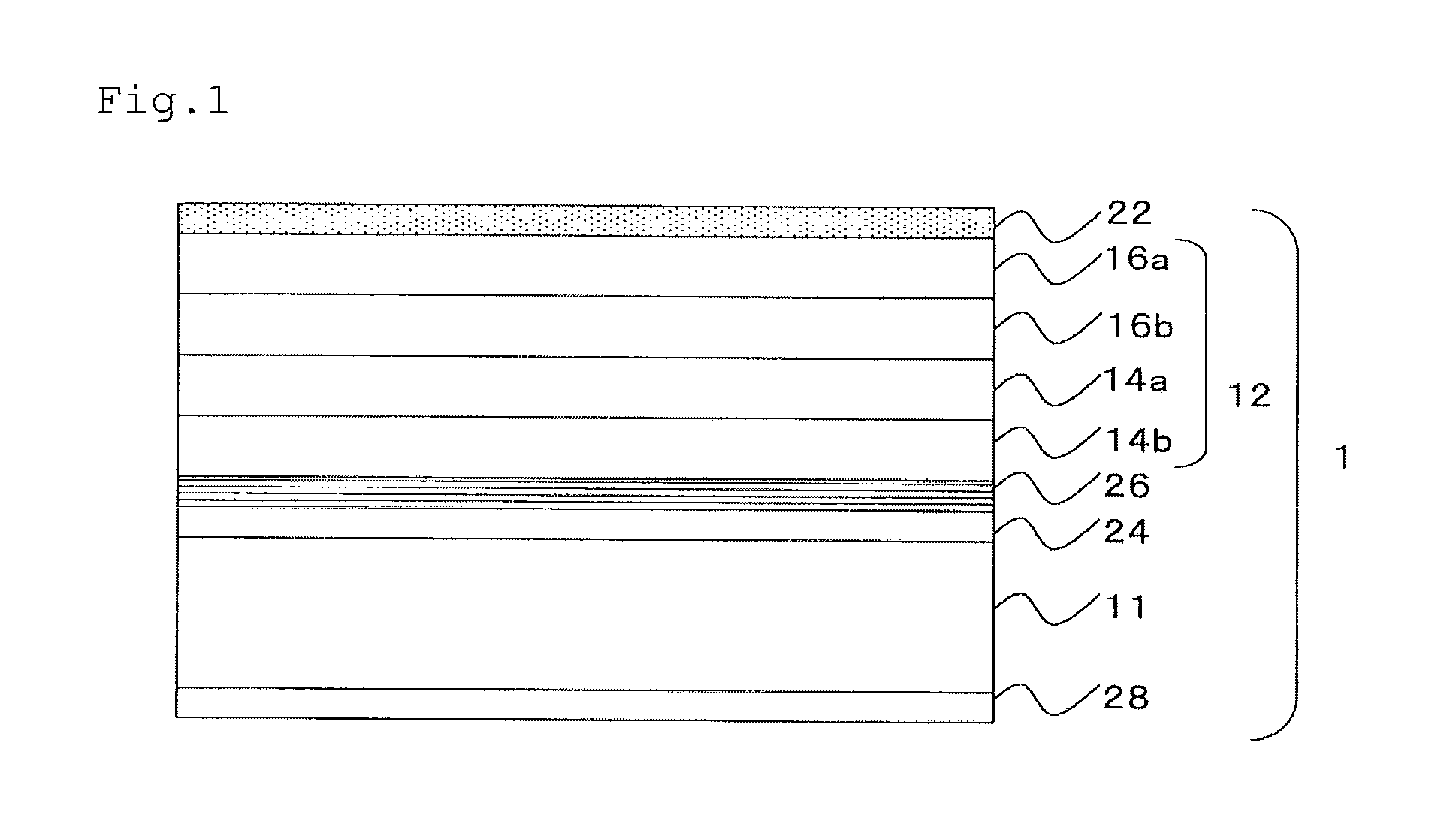
[0164]Using a wire bar, the back layer coating liquid (U) was applied onto a PET film (by FUJIFILM, having a thickness of 188 μm) so that the thickness of the coating layer after dried could be 0.5 μm. Subsequently, this was heated at 150° C. for 10 minutes, dried and solidified to form a back layer.

[0165]Next, using a wire bar, the underlayer coating liquid (S) was applied to the surface of the back layer-having PET film, as prepared in the above, on the side thereof not having the back layer so that the thickness of the coating layer after dried could be 0.25 μm. Subsequently, this was heated at 150° C. for 10 minutes, dried and solidified to form an undercoat layer.

[0166]Next, using a wire bar, the alignment layer coating liquid (H) was applied onto the formed undercoat layer so that the thickness of the coating layer after dried could be 1.0 μm. Subsequently, this was heated at 100° C. for 2 minutes, dried and solidified to form an alignment layer. The alignment layer was rubbed...

example 2

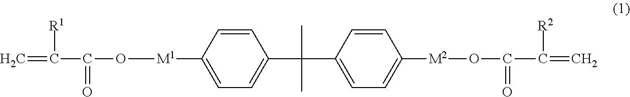
[0192]Liquid crystal composition coating liquids (R21), (R22), (L21) and (L22) were prepared in the same manner as that for the liquid crystal composition coating liquids (R11), (R12), (L11) and (L12), except that the polyfunctional polymerizable compound (1) (molecular weight: 513) was changed to the following polyfunctional polymerizable compound (2) (molecular weight: 336). The viscosity at 23° C. of the coating liquids was 2.9 mPa·s, 2.9 mPa·s, 3.2 mPa·s and 3.1 mPa·s, respectively.

Polymerizable Compound (2):

[0193]

[0194]An infrared light reflector of Example 2 was produced according to the same process as in Example 1, except that the liquid crystal composition coating liquids (R21), (R22), (L21) and (L22) were used in place of (R11), (R12), (L11) and (L12).

example 3

[0195]Liquid crystal composition coating liquids (R31), (R32), (L31) and (L32) were prepared in the same manner as that for the liquid crystal composition coating liquids (R11), (R12), (L11) and (L12), except that the polyfunctional polymerizable compound (1) was changed to the following polyfunctional polymerizable compound (3) (molecular weight: 424). The viscosity at 23° C. of the coating liquids was 3.6 mPa·s, 3.5 mPa·s, 3.9 mPa·s and 3.8 mPa·s, respectively.

Polymerizable Compound (3):

[0196]

[0197]An infrared light reflector of Example 3 was produced according to the same process as in Example 1, except that the liquid crystal composition coating liquids (R31), (R32), (L31) and (L32) were used in place of (R11), (R12), (L11) and (L12).


PUM


Abstract

An infrared light reflector having an infrared light reflective layer formed by polymerizing an infrared light reflective layer composition that contains a polyfunctional polymerizable compound, a cholesteric liquid crystal compound and a fluorine-containing alignment controlling agent in an amount of at least 60 ppm relative to the liquid crystal compound, wherein when a functional layer composition is applied onto at least one surface of the infrared light reflective layer, the number of the coating liquid cissing defects having a diameter of at least 5 μm is at most 10/m2.

Description

CROSS-REFERENCE TO RELATED APPLICATIONS[0001]The present application claims the benefit of priority from Japanese Patent Application No. 2010-187305, filed on Aug. 24, 2010, the contents of which are herein incorporated by reference in their entirety.BACKGROUND OF THE INVENTION[0002]1. Field of the Invention[0003]The present invention relates to an infrared light reflector. Precisely, the invention relates to an infrared light reflector having an infrared light reflective layer containing a cholesteric liquid crystal compound, which is used mainly for heat shields for windowpanes in buildings, vehicles, etc.[0004]2. Description of the Related Art[0005]Recently, with the increase in the interest in environment and energy, the needs for energy-saving industrial products are high, and as one of them, glass and films are desired that are effective for heat shields for windowpanes in houses, cars and the like, or that is, for reducing thermal load from sunlight through windowpanes. For r...

Claims


Application Information

Patent Timeline
Patent Type & Authority Applications(United States)
IPC IPC(8): G02B5/26B05D5/06G02B5/30
CPCC09K19/14C09K19/56G02B5/208C09K2219/03G02B5/26C09K2019/0448
Inventor WATANABE, HIDETOSHI
Owner FUJIFILM CORP
Why Eureka
Try Eureka