Compliant printed flexible circuit

Active Publication Date: 2012-03-08
HSIO TECH
View PDF20 Cites 65 Cited by
  • Summary
  • Abstract
  • Description
  • Claims
  • Application Information

AI Technical Summary

Benefits of technology

[0007]The present disclosure is directed to a high performance compliant printed flexible circuit (“CFPC”) that will enable next generation electrical pe

Problems solved by technology

In general, flexible circuits are expensive compared to some rigid PCB products.
Flexible circuits also have some limitation

Method used


Image

  • Compliant printed flexible circuit
  • Compliant printed flexible circuit
  • Compliant printed flexible circuit

Examples


Embodiment Construction

[0047]A complaint printed flexible circuit according to the present disclosure may permit fine contact-to-contact spacing (pitch) on the order of less than 1.0 mm pitch, and more preferably a pitch of less than about 0.7 millimeter, and most preferably a pitch of less than about 0.4 millimeter. Such fine pitch compliant printed flexible circuits are especially useful for communications, wireless, and memory devices.

[0048]The present compliant printed flexible circuit can be configured as a low cost, high signal performance interconnect assembly, which has a low profile that is particularly useful for desktop and mobile PC applications. IC devices to be installed and uninstalled without the need to reflow solder. The solder-free electrical connection of the IC devices is environmentally friendly.

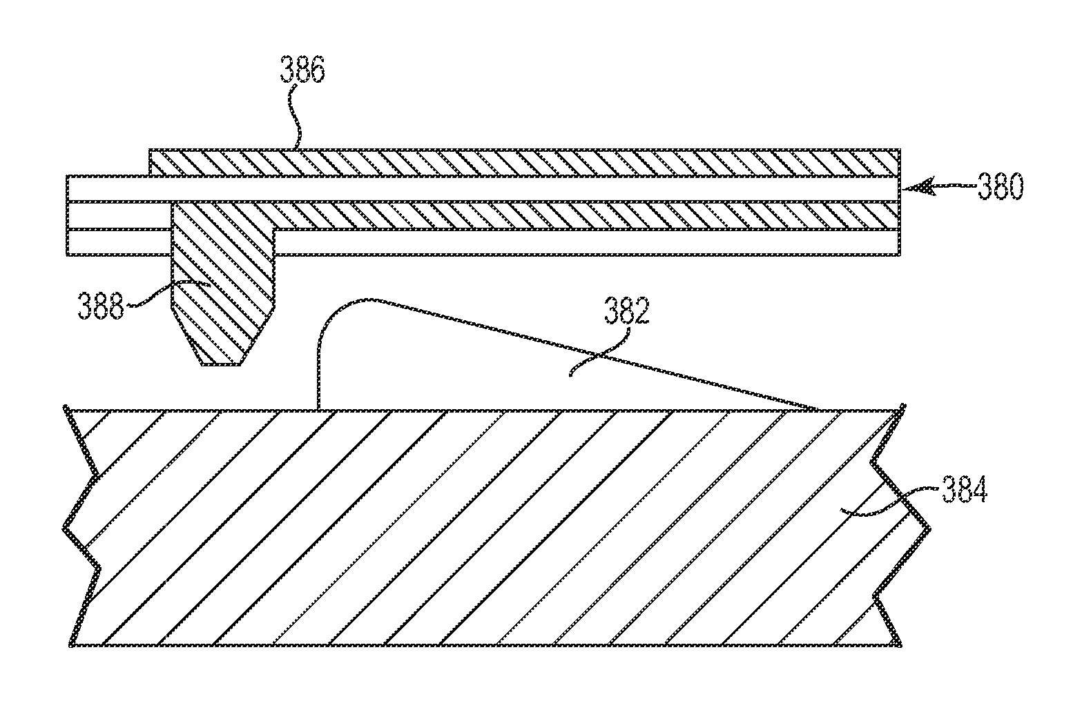
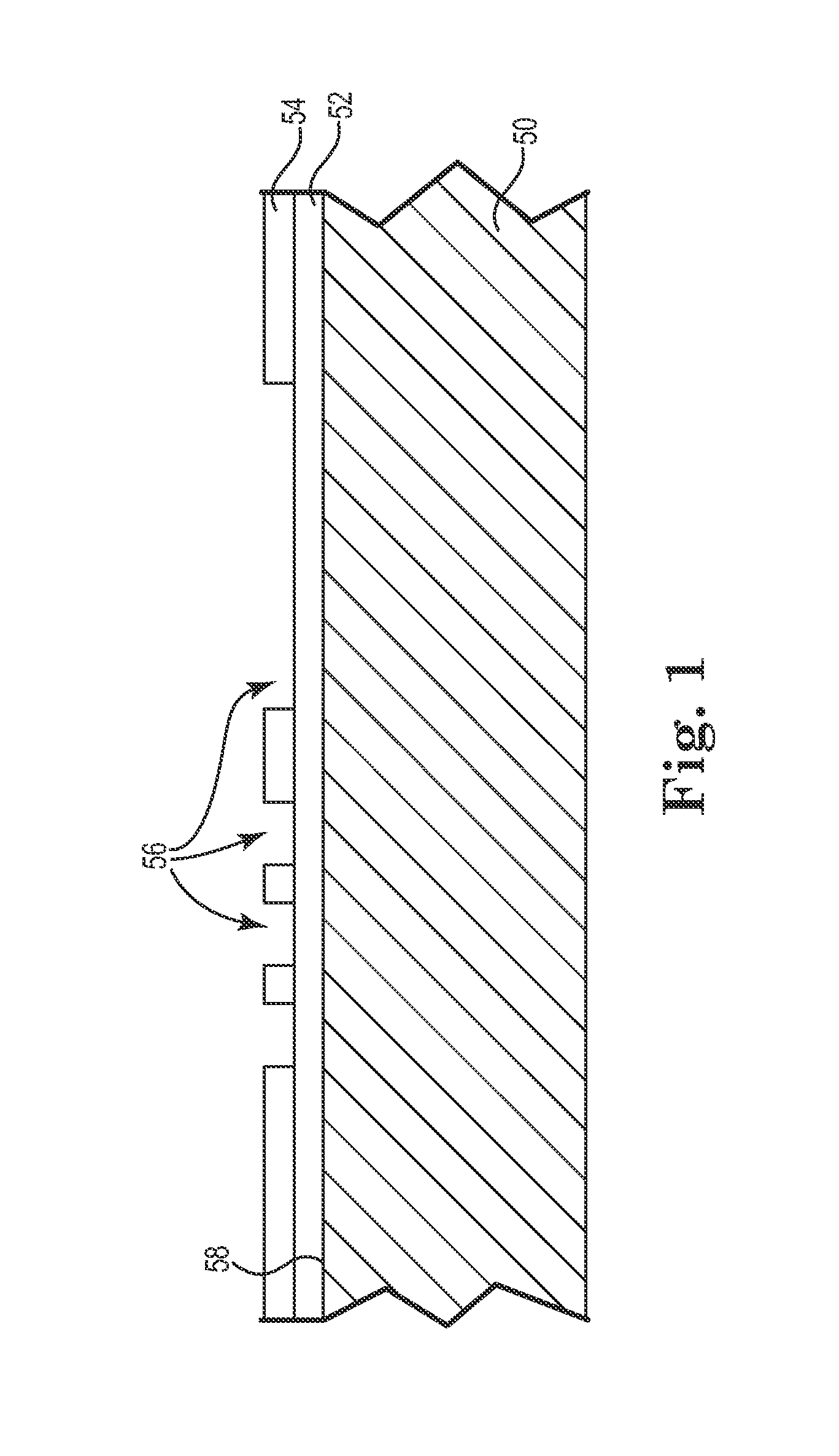
[0049]FIG. 1 is a side cross-sectional view of a method for replicating a flexible circuit member using additive processes in accordance with an embodiment of the present disclosure. Flexible...


PUM

PropertyMeasurementUnit
Flexibilityaaaaaaaaaa
Shapeaaaaaaaaaa
Electrical conductoraaaaaaaaaa

Abstract

A compliant printed flexible circuit including a flexible polymeric film and at least one dielectric layer bonded to the polymeric film with recesses corresponding to a target circuit geometry. A conductive material is printed in at least a portion of the recesses to form a circuit geometry. At least one dielectric covering layer is printed over at least the circuit geometry. Openings can be printed in the dielectric covering layer to provide access to at least a portion of the circuit geometry.

Description

TECHNICAL FIELD[0001]The present application relates to a high performance compliant printed flexible circuit that merges the long-term performance advantages of flexible circuits, with the flexibility of additive printing technology.BACKGROUND OF THE INVENTION[0002]Traditional printed circuits are often constructed in what is commonly called rigid or flexible formats. The rigid versions are used in nearly every electronic system, where the printed circuit board (PCB) is essentially a laminate of materials and circuits that when built is relatively stiff or rigid and cannot be bent significantly without damage.[0003]Flexible circuits have become very popular in many applications where the ability to bend the circuit to connect one member of a system to another has some benefit. These flexible circuits are made in a very similar fashion as rigid PCB's, where layers of circuitry and dielectric materials are laminated. The main difference is the material set used for construction. Typi...

Claims


Application Information

Patent Timeline
IPC IPC(8): H05K1/02H05K3/10
CPCH01L23/4985Y10T29/49155H01L2924/12044H01L2924/3011H05K1/0221H05K1/0274H05K1/118H05K1/16H05K3/107H05K3/1258H05K3/207H05K3/246H05K3/28H05K3/4007H05K3/4664H05K2201/0367H05K2201/09109H01L2224/16H01L2924/09701B33Y80/00H05K1/0216H05K1/0256H05K1/0284H05K1/181H05K3/4694H05K2201/0344H05K2201/10674H05K2201/10734
Inventor RATHBURN, JAMES
Owner HSIO TECH
Why Eureka
Try Eureka