Titania-doped quartz glass and making method

a technology of quartz glass and doped glass, which is applied in the direction of glass deposition burners, manufacturing tools, instruments, etc., can solve the problems of quartz glass undergoing thermal hysteresis, glass having a tiosub>, and specific ranges that are still insufficien

Active Publication Date: 2012-03-08
SHIN ETSU CHEM IND CO LTD
View PDF12 Cites 9 Cited by
  • Summary
  • Abstract
  • Description
  • Claims
  • Application Information

AI Technical Summary

Benefits of technology

[0028]One embodiment of the invention is a titania-doped quartz glass having a minimal distribution of absorption edge wavelength at an apparent transmittance per 5-mm thickness, which is best suited for use as EUV lithography members.

Problems solved by technology

Continuing a study on a titania-doped quartz glass for EUV lithography optical members, the inventors found that quartz glass having a TiO2 concentration, refractive index, OH group concentration, birefringence, and internal transmittance in 300-3,000 nm range adjusted to their specific ranges is still insufficient as the EUV lithography optical member.
Particularly when the absorption edge wavelength is not uniform and has a distribution, the quartz glass tends to undergo thermal hysteresis during service as the EUV lithography member.

Method used


Image

  • Titania-doped quartz glass and making method
  • Titania-doped quartz glass and making method
  • Titania-doped quartz glass and making method

Examples


example 1

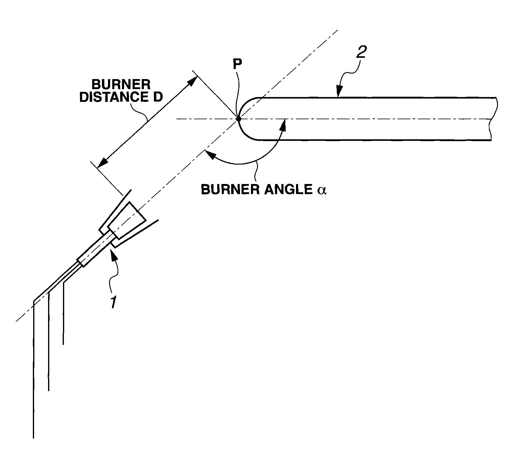
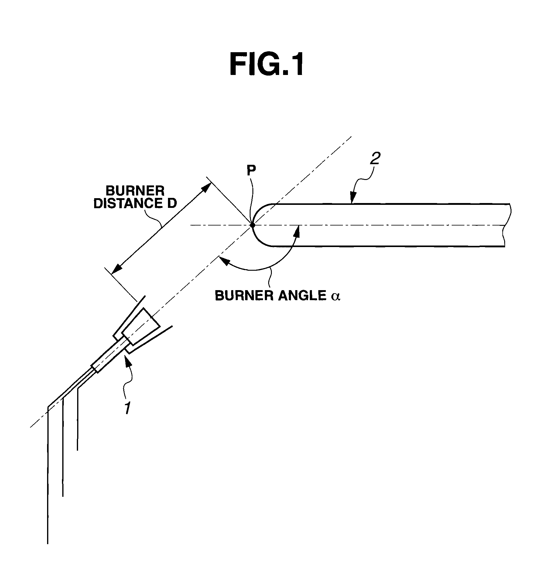
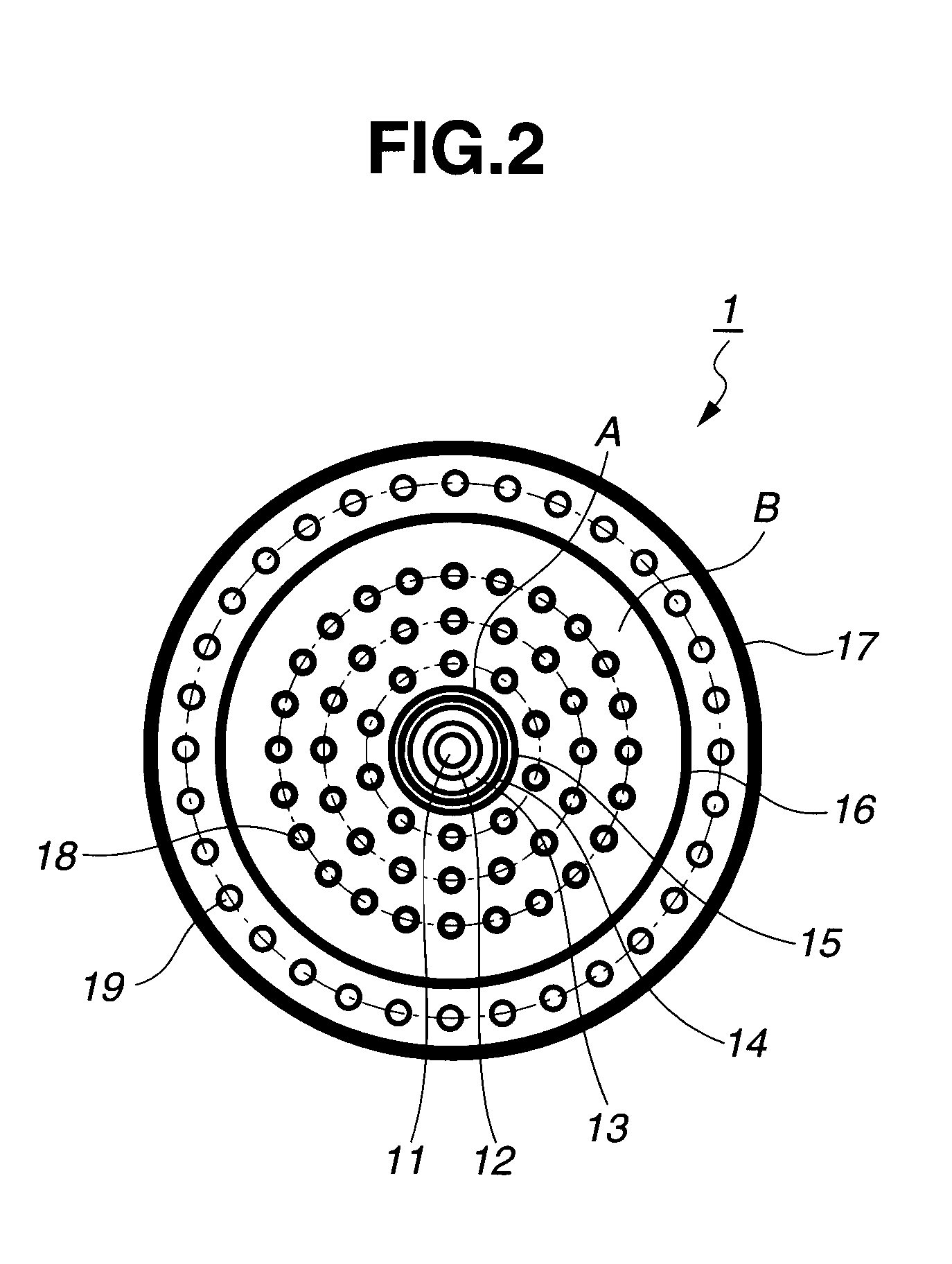
[0081]A titania-doped quartz glass ingot was prepared by using a furnace including a burner as shown in FIG. 2, feeding gases (SiCl4, TiCl4, O2, H2) to respective nozzles of the burner as shown in Table 1, forming an oxyhydrogen flame, effecting oxidation or flame hydrolysis of silicon tetrachloride and titanium tetrachloride in the oxyhydrogen flame to produce SiO2 and TiO2, depositing silica and titania fine particles on a target, and concurrently melting and vitrifying the particles. The target was disposed forward of the burner, rotated at 50 rpm, and retracted at 10 mm / hr. The burner and the target were relatively set at a burner distance and a burner angle as shown in Table 1. Table 1 also reports a H2 / O2 ratio and a linear velocity of hydrogen gas flows in the central multi-fold tube section and the multi-nozzle section under the process conditions. The flow rates of respective gases were kept at a variation of ±0.2% by volume. During preparation of titania-doped quartz glass...

examples 2 , 3 , 4 , 6

Examples 2, 3, 4, 6, and Comparative Examples 1, 2

[0087]Titania-doped quartz glass ingots were prepared with the gas flow rates, burner distance and burner angle set as described in Table 1. The remaining conditions were the same as in Example 1.

example 5

[0088]A titania-doped quartz glass ingot was prepared with the gas flow rates, burner distance and burner angle set as described in Table 1. After the ingot was shaped, it was annealed in a muffle furnace of ceramic fiber body by holding in air at 1,120° C. for 150 hours and slowly cooling at a rate of 5° C. / hr to 500° C. The remaining conditions were the same as in Example 1.

[0089]The titania-doped quartz glass samples prepared in Examples 1, 2 and 3 displayed better values of absorption edge wavelength distribution, absorption edge wavelength position, apparent transmittance at 350 to 800 nm, total content of metal impurities, hydrogen molecule concentration, TiO2 concentration, zero expansion temperature, fictive temperature, fictive temperature distribution, OH group concentration reduction and OH group concentration after 900° C. / 100-hr heat treatment. They were satisfactory as the EUV lithography member.

[0090]The titania-doped quartz glass sample prepared in Example 4 displaye...


PUM

PropertyMeasurementUnit
distanceaaaaaaaaaa
angleaaaaaaaaaa
linear velocityaaaaaaaaaa

Abstract

A titania-doped quartz glass suited as an EUV lithographic member is prepared by feeding a silicon-providing reactant gas and a titanium-providing reactant gas through a burner along with hydrogen and oxygen, subjecting the reactant gases to oxidation or flame hydrolysis to form synthetic silica-titania fine particles, depositing the particles on a rotating target, and concurrently melting and vitrifying the deposited particles to grow an ingot of titania-doped quartz glass. The target is retracted such that the growth front of the ingot may be spaced a distance of at least 250 mm from the burner tip.

Description

CROSS-REFERENCE TO RELATED APPLICATION[0001]This non-provisional application claims priority under 35U.S.C. §119(a) on Patent Application No. 2010-196557 filed in Japan on Sep. 2, 2010, the entire contents of which are hereby incorporated by reference.TECHNICAL FIELD[0002]This invention relates to titania-doped quartz glass suited for use in the EUV lithography, and a method for manufacturing the same.BACKGROUND ART[0003]In the advanced lithography process for the fabrication of semiconductor devices, a light source of shorter wavelength is used for exposure. A subsequent transition to lithography using extreme ultraviolet (EUV) is regarded promising. Since the EUV lithography uses a reflecting optical system, the lithography accuracy can be adversely affected even by a slight thermal expansion of each member (e.g., substrate) in the lithographic optical system induced by the heat that has reached there. Accordingly, members like reflecting mirrors, masks, and stages must be made of...

Claims


Application Information

Patent Timeline
Patent Type & Authority Applications(United States)
IPC IPC(8): C03C14/00G03F1/00C03B19/00
CPCC03B19/1423C03B19/1453C03B2201/23C03B2201/42C03B2207/06C03B2207/12C03C2201/42C03B2207/62C03B2207/64C03C3/06C03C4/0085C03C2201/21C03B2207/20C03B20/00C03B32/00C03C8/12
Inventor MAIDA, SHIGERUOTSUKA, HISATOSHISEKIZAWA, OSAMUYANAGISAWA, NAOKI
Owner SHIN ETSU CHEM IND CO LTD
Why Eureka
Try Eureka