
Piezoelectric Component

a technology of piezoelectric actuators and components, applied in piezoelectric/electrostrictive/magnetostrictive devices, piezoelectric/electrostriction/magnetostriction machines, electrical equipment, etc., can solve problems such as uncontrolled cracking and failure of piezoelectric actuators, and achieve the effect of avoiding or reducing uncontrolled cracking

Inactive Publication Date: 2012-03-15
EPCOS AG
View PDF7 Cites 1 Cited by
  • Summary
  • Abstract
  • Description
  • Claims
  • Application Information

AI Technical Summary

Benefits of technology

[0006]In one aspect, a piezoelectric component is specified which avoids or at least reduces uncontrolled cracking.
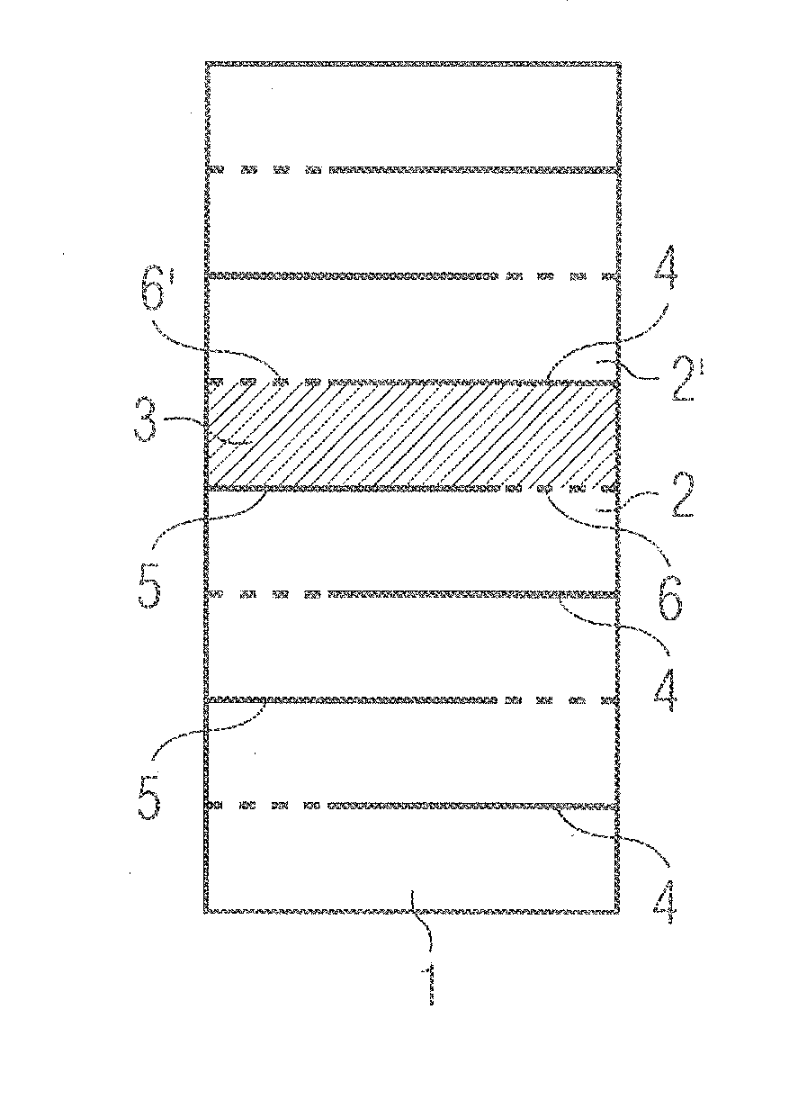
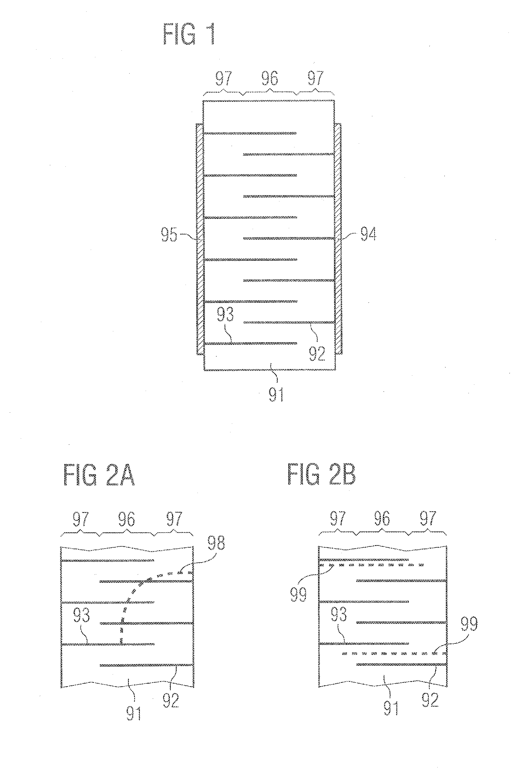
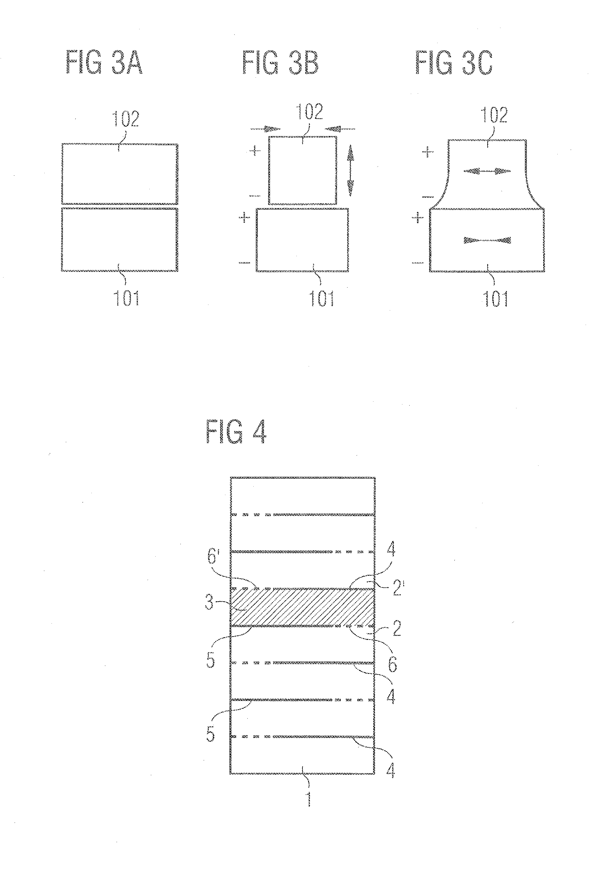
[0011]By means of the first and second piezoelectric layers having different coercive field strengths, by way of example, during thermal treatments, during metallization, during soldering, during the polarization process and / or during the operation of the piezoelectric component, local elastic stresses can be produced in the stack of the piezoelectric component, which stresses are intended to lead to the targeted cracking. By virtue of the at least one first and one second piezoelectric layer introduced in a defined manner, different polarization states for instance during the polarization process at the contact boundary between the first and second piezoelectric layers can lead to polarization cracks. The polarization cracks run parallel or substantially parallel to the electrode layers. Uncontrolled crack growth transversely with respect to the electrode layers is thus prevented, without porous structures known from the prior art, for instance, having to be introduced into the piezoelectric component.
[0012]The first and second piezoelectric layers can have different coercive field strengths by virtue of the fact that they differ in their composition, which can mean, in particular, that they comprise different ceramic materials, different dopants, different dopant concentrations or different particle sizes of starting materials respectively used. Furthermore, the first and second piezoelectric layers can have different layer thicknesses. In order to produce the first and second piezoelectric layers with different coercive field strengths, they can differ in exactly one of the abovementioned properties or else in a plurality of the abovementioned properties. In this case, according to the inventors' insight, it can be advantageous with regard to the processability and the economic viability of the production process if the first and second piezoelectric layers differ in exactly one or just a few of the abovementioned properties. The greater the number of properties differentiating the first and second piezoelectric layers, the greater, on the other hand, however, the degree of freedom in the production of the first electric coercive field strength can advantageously also be in comparison with the second electric coercive field strength.
[0017]Selection of a ceramic material for the first and second piezoelectric layers which is identical with regard to its constituents and which differs in the concentration of at least one constituent for the first and second piezoelectric layers affords the advantage that precise control of the elastic stresses at the contact boundary, that is to say the interface, between the first and second piezoelectric layers is made possible. Furthermore, it is possible to adapt the first and second coercive field strengths by means of the difference in the concentration of the at least one constituent, that is to say, in the example described above, for instance by means of the change in the titanium content. Furthermore, additionally added dopants can be present in identical dopant concentrations in this case. This can afford particular advantages during the processing of the piezoelectric component, since possible chemical inhomogeneities between the first and second piezoelectric layers can be minimized and can thus be minimal in the piezoelectric component and therefore have no influence on the sintering behavior of the piezoelectric layers. In particular in the case of different dopants and / or dopant concentrations, the sintering behavior of ceramic materials can be greatly changed, such that specific adaptation of the sintering shrinkage between such different materials is then necessary.
[0018]Furthermore, the first and second piezoelectric layers can differ in their composition to the effect that the first and second piezoelectric layers comprise ceramic materials produced from starting powders having different particle sizes. The ceramic layers of a piezoelectric component are typically produced from so-called green sheets, which comprise unsintered ceramic powder alongside further constituents such as, for instance, sintering auxiliaries, wherein the green sheets are subsequently joined together with the electrode layers and sintered. The inventors have discovered that ceramic materials which are identical for instance in their chemical composition and differ in the starting sizes of the powders before the sintering process are suitable for producing the first and second piezoelectric layers. Ceramic materials comprising a coarser starting powder usually have coarser grains after the conclusion of the sintering process, which can lead to a reduction of the coercive field strength.

Problems solved by technology

Upon transition into the active region, the cracks can bend away in an uncontrolled manner.
If a crack bridges at least two electrodes in this case, short circuits can arise, which leads to the failure of the piezoelectric actuator.

Method used


Image

  • Piezoelectric Component
  • Piezoelectric Component
  • Piezoelectric Component

Examples


Embodiment Construction

[0063]FIG. 1 illustrates a known multilayered piezoelectric actuator comprising a stack 91 having a plurality of layers of a piezoelectric material with internal electrodes 92, 93 between the piezoelectric layers. In this case, the same piezoelectric material is used in the entire actuator. The internal electrodes 92, 93 are in each case embodied in a type of comb structure in the form of intermeshed combs. By means of contact areas in the form of metallizations 94, 95 at the outer side of the stack 91, an electrical voltage can be applied between the internal electrodes 92, 93. In the active region 96 of the stack 91, in which the internal electrodes 92, 93 are arranged alternately one above another, a piezoelectric stroke can be effected by an expansion of the piezoelectric material of the actuator. In the inactive regions 97 of the stack 91, only a very small electric field is built up by the application of an electrical voltage to the internal electrodes 92, 93, such that in the...


PUM


Abstract

A piezoelectric component includes a stack of piezoelectric layers arranged one on top of the other and first and second electrode layers arranged therebetween. The stack includes at least one first piezoelectric layer having a first electrical coercive force and directly adjacent thereto at least one second piezoelectric layer having a second electrical coercive force different from the first coercive force.

Description

[0001]This application is a continuation of co-pending International Application No. PCT / EP2010 / 056912, filed May 19, 2010, which designated the United States and was not published in English, and which claims priority to German Application No. 10 2009 023 356.3, filed May 29, 2009 and to German Application No. 10 2009 043 220.5, filed Sep. 28, 2009, each of which is incorporated herein by reference.TECHNICAL FIELD[0002]A piezoelectric component comprising piezoelectric layers is specified.BACKGROUND[0003]Piezoelectric components such as, for instance, multilayered piezoelectric actuators consist of a plurality of layers of a piezoelectric material with internal electrodes between the piezoelectric layers. Usually, the same piezoelectric material is used in the entire actuator. Piezoelectric actuators furthermore have a multiplicity of internal electrodes which are arranged one above another and are contact-connected with alternate electrical polarity and between which the piezoelec...

Claims


Application Information

Patent Timeline
Patent Type & Authority Applications(United States)
IPC IPC(8): H01L41/047H10N30/00H10N30/50H10N30/85H10N30/87H10N30/01H10N30/045H10N30/05H10N30/093H10N30/20H10N30/853
CPCH01L41/1876H01L41/0838H10N30/508H10N30/8554
Inventor GLAZUNOV, ALEXANDERDERNOVSEK, OLIVER
Owner EPCOS AG
Learn More