Dc-dc converters

Inactive Publication Date: 2012-03-15
CIRRUS LOGIC INT SEMICON
View PDF9 Cites 66 Cited by
  • Summary
  • Abstract
  • Description
  • Claims
  • Application Information

AI Technical Summary

Benefits of technology

[0011]In another aspect of the invention there is provided a method of reducing power loss in a DC-DC converter having at least one power switch, the method comprisin

Problems solved by technology

These different functions may result in different load current demands.
For instance if a multi-function device is being used as a gaming platform the processing load may be hig

Method used


Image

  • Dc-dc converters
  • Dc-dc converters
  • Dc-dc converters

Examples


Example

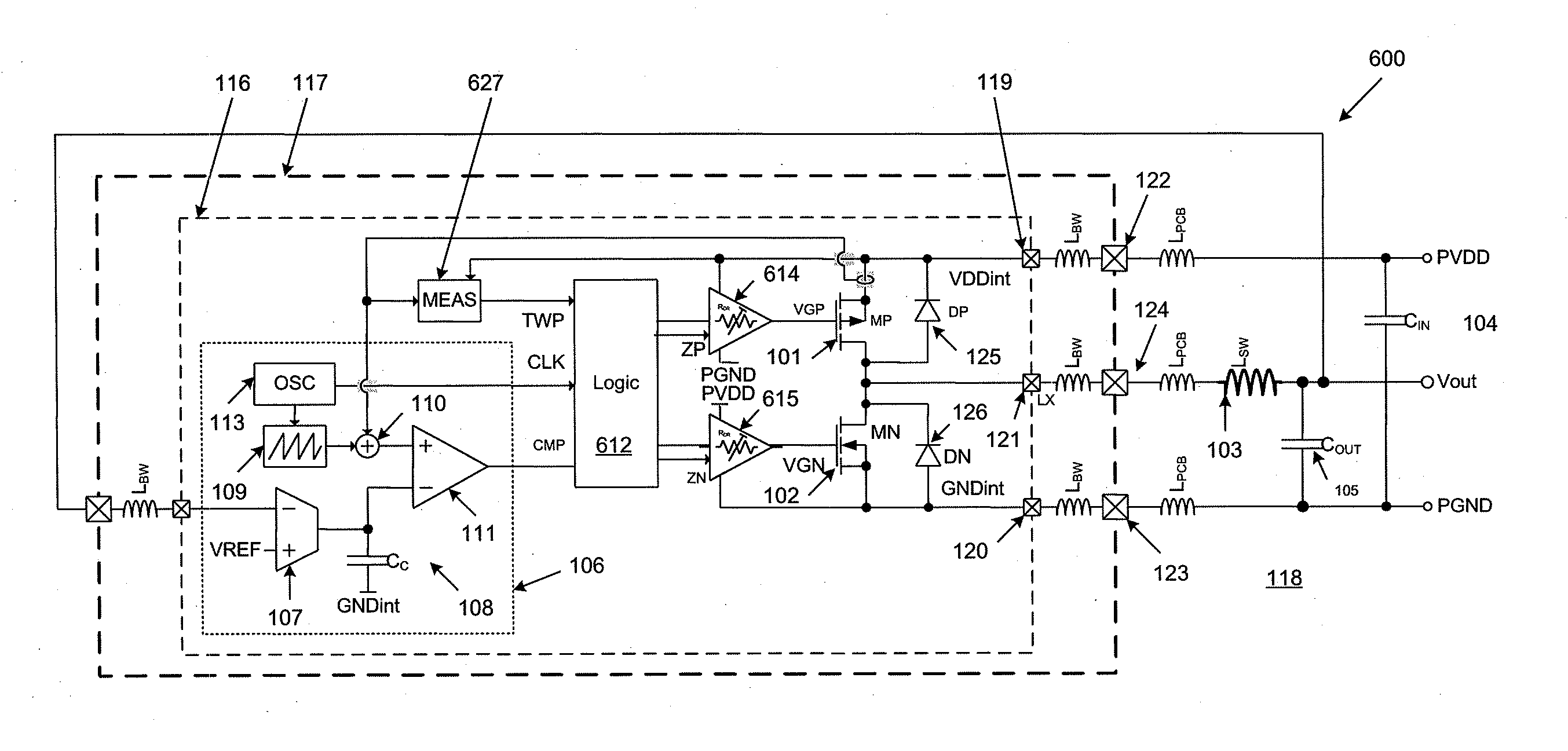
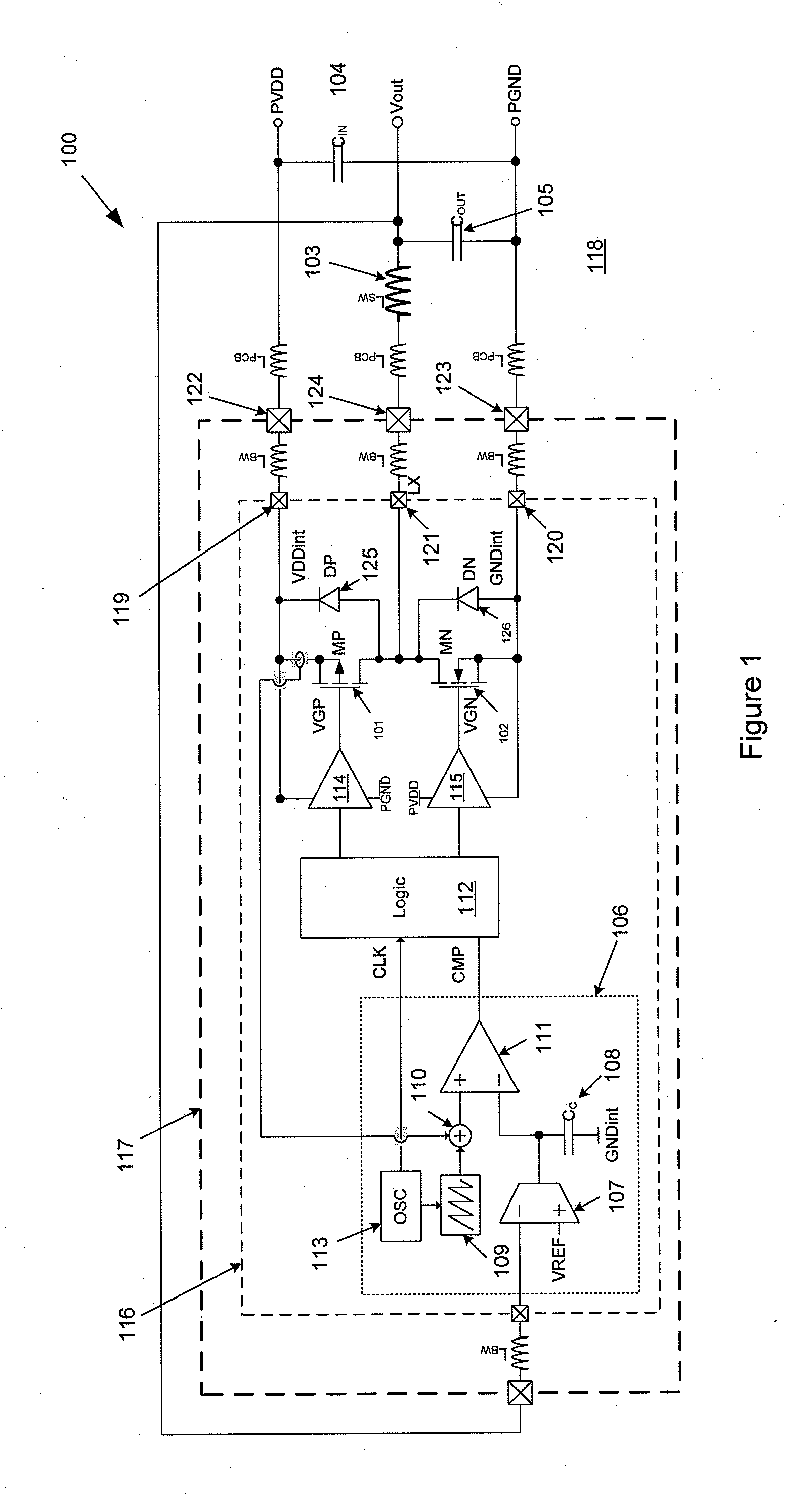
[0035]Referring to FIG. 1 an example of a conventional synchronous DC-DC buck converter circuit 100 is shown. A high-side power switch 101, in this case a PMOS switch, is connected between a supply node connected to high-side supply, PVDD, and a common inductor node, LX. A low-side power switch 102, in this case an NMOS switch, is connected between the common inductor node LX and a low-side node connected to a low-side or ground supply, PGND. An inductor 103 is connected between the inductor node LX and the output, Vout. An input decoupling capacitor 104 is connected between the input high-side supply and ground supply and an output smoothing capacitor 105 is connected between the output and ground supply. Single capacitors 104 and 105 are shown in FIG. 1 but it will be appreciated that either or both of these capacitances could be provided by multiple capacitors in combination.

[0036]Servo control circuitry 106 receives a feedback signal from the output voltage. This embodiment of a...


PUM


Abstract

This application relates to switch mode DC-DC converter circuitry having a power switch operably connected between a supply node and an inductor node. The DC-DC converter has switch control circuitry for driving the power switch which is configured to controllably vary the rate of at least one of turn-on or turn-off of the first power switch. The rate may be based on the operational conditions of the converter, e.g. inductor current, one or more supply voltages and/or operating mode or activity level of a host device. By increasing the rate at which the switch turns-on or off switch transition power losses can be reduced. However a faster switching speed can lead to an increased voltage stress on the circuitry. Embodiments of the present invention varying the rate or turn-on and/or turn-off of the switch to reduce power losses but remain with the safe operating limits for the circuitry.

Description

[0001]This application claims the benefit of U.S. Provisional Application Ser. No. 61 / 381,517, filed Sep. 10, 2010, the entire disclosure of which is herein incorporated by reference.BACKGROUND OF THE INVENTION[0002]DC-DC switch-mode converters are increasingly being used in electronic equipment, e.g. as high-efficiency replacements for linear voltage regulators, especially for portable electronic equipment.[0003]Many modern electronic devices may provide multiple different functions. For example a device may be useable as a mobile phone, a video player, an audio player and / or a gaming platform. These different functions may result in different load current demands. For instance if a multi-function device is being used as a gaming platform the processing load may be high which will typically lead to a relatively high load current demand whereas if the device is being used purely for audio playback the load current demand may be relatively low.[0004]In order to ensure overall system ...

Claims


Application Information

Patent Timeline
IPC IPC(8): G05F1/46H03B1/00
CPCH02M3/156H02M1/0029
Inventor HAIPLIK, HOLGERSADATI, SEYED HAMEDMCCLOY-STEVENS, MARK JAMES
Owner CIRRUS LOGIC INT SEMICON
Why Eureka
Try Eureka