Fluid-working machine valve timing

a technology of working machine valve timing and valve body, which is applied in the direction of valve details, operating means/releasing devices of valves, liquid fuel engines, etc., can solve the problems of machine failure, machine malfunction, and inability to complete the motor cycle, and achieve the effect of accurate specification

Active Publication Date: 2012-03-15
ARTEMIS INTELLIGENT POWER
View PDF9 Cites 3 Cited by
  • Summary
  • Abstract
  • Description
  • Claims
  • Application Information

AI Technical Summary

Benefits of technology

[0015]By controlling the timing of the opening or closing of the low pressure or high pressure valve (the said variably timed valve) taking into account one or more properties of the performance of the fluid working machine during an earlier cycle of working chamber volume, the machine can better adapt to varying properties of the working fluid and the components of the fluid working machine itself and run closer to the point at which the variably timed valve would fail to open or close correctly than would otherwise be the case. This method is also preferable to methods in which the timing of the opening or closing of the variably timed valve (e.g. phase relative to cycles of working chamber volume) is delayed from one cycle to the next until a failure occurs and then brought forward so that opening or closing occurs before that failure point. The method of invention is preferable as it avoids failures of a valve to open or close, which may not remediable and may allow a smaller margin for error in the time (e.g. phase) between the opening or closing of the variably timed valve and the time at which a failure to open or close would occur. Thus, the method may comprise predicting a time (such as the phase within a cycle of working chamber volume) at which the variably timed valve would fail to open or close correctly and ensuring that the variable timed valve is commanded to open or close before that time.
[0044]It may be that the variably timed valve is one of the low pressure valve and the high pressure valve and the timing of the closing of the variably timed valve is optimised to maximise either or both of the efficiency and smoothness of the fluid working machine while avoiding failure of the other of the low pressure valve and the high pressure valve to open later in the same cycle of working chamber volume. It may be that the variable timed valve is instructed to open or close, as appropriate, a period of time before the latest determined time at which it could be instructed in order to open or close correctly, which period of time is initially relatively long relative to the period of cycles of working chamber volume when the machine is caused to start operating and which then decreases relative to the period of cycles of working chamber volume as operation continues, as the necessary margin of safety to avoid a failure of the variably timed valve to open or close during a specific cycle of working chamber volume may be decreased as additional measurements of properties are made, or trends in measured properties are calculated, or properties of the machine (e.g. temperature) stabilise.
[0049]Where the working chamber is a piston-cylinder having a generally fixed end and a moving end (for example, in the case of a radial or axial piston machine), the primary low pressure valve is preferably provided at the fixed end of the cylinder, to minimise movement of the primary low pressure valve. The primary low pressure valve may be coaxial with the cylinder or extend radially from the cylinder at the fixed end of the cylinder. The high pressure valve is typically also provided at the fixed end of the cylinder, typically either coaxially with or extending radially from the low pressure valve. In these arrangements, the secondary low pressure port is preferably provided at the opposite end of the cylinder. This has the advantage of causing an exchange of fluid in all parts of the cylinder on each cycle, reducing hot spots in the fluid around the base of the cylinder. For example, the secondary low pressure port may be coaxial with or extend radially from the cylinder, at the moving end of the cylinder.
[0071]The timing of the opening or closing of the variably timed valve can therefore be controlled taking into account not only the instantaneous sensed pressure but also at least one additional parameter which varies in use. This enables the opening or the closing of the variably timed valve to be actuated closer to the point at which the opening or closing might fail, or might cause another valve to fail to open or close (typically passively). For example, it might enable the closure of the low pressure valve in a pumping cycle to be delayed further than would otherwise be the case, while still ensuring that the low pressure valve closes in time to enable the high pressure valve to open. Otherwise, it would be necessary to close the low pressure valve at an earlier time in order to ensure that the high pressure valve opens and thereby avoid failure. Furthermore, it can allow the volume of fluid displaced during each cycle to be more accurately specified than would otherwise be the case if there was variation in the precise timing of the opening or closing of the variably timed valve due to additional parameters which vary in use.
[0095]The experimental optimisation and computer simulation processes may comprise varying the properties of the working fluid such that the additional parameter varies, adjusting the timing of the opening and closing of the variably timed valves, measuring the operation of the fluid working machine, and recording the timing values and the additional parameter, when the operation of the fluid working machine is optimised, into the stored data. The experimental optimisation may be carried out for each fluid working machine, or for each materially different design of fluid working machine. Typically, there is more than one said additional parameter. Typically, the optimisation is such that the net displacement of fluid from a low pressure to a high pressure manifold or vice versa, is maximised, for the full range of expected operating conditions which are not measured by the additional parameters.

Problems solved by technology

It is possible for these machines to fail if the timing of valve closure is not correct for the fluid pressure in the high pressure manifold.
Thus the motoring cycle is not possible and the machine malfunctions.
In a second example, if the high pressure valve closes too late in the expansion stroke of a motoring cycle, this prevents the working chamber from sufficiently decompressing, thus preventing the respective low pressure valve from reopening to exhaust fluid from the working chamber and therefore causing fluid to be returned to the high pressure manifold on the compression stroke.
Additionally the performance of the valves and other moving components can change over time as they wear, bed in or distort, or at different temperatures, causing them to individually act faster or slower at different times. Still further problems arise as fluid properties and valve performance are very difficult or expensive to measure during operation.
Finally, it may be expensive to measure individual working chamber characteristics (such as leakage and valve closure times) during manufacture, and thus it may be desired to avoid calibrating the fluid working machine until it is used.
These factors conspire to reduce the accuracy of the flow into or out of the working machines, which is otherwise very accurately known.
Changes in the fluid properties can even cause the fluid working machine to fail in operation.
For example an uncompensated increase in fluid compressibility or leakage would may mean that a low pressure poppet valve would close too late to sufficiently pressurise the working chamber and then open the high pressure valve in preparation for a motoring cycle.
Thus the motoring cycle is not possible and the machine malfunctions.
However, this reduces the efficiency and capability of the machine because less fluid is displaced than would be the case were the timing less conservative.
Also the closure of high and low pressure valves at times of higher flow creates more noise and could reduce the life of the valves, and can create undesirable torque and pressure ripple in the flow output of the fluid working machine.

Method used


Image

  • Fluid-working machine valve timing
  • Fluid-working machine valve timing
  • Fluid-working machine valve timing

Examples


Embodiment Construction

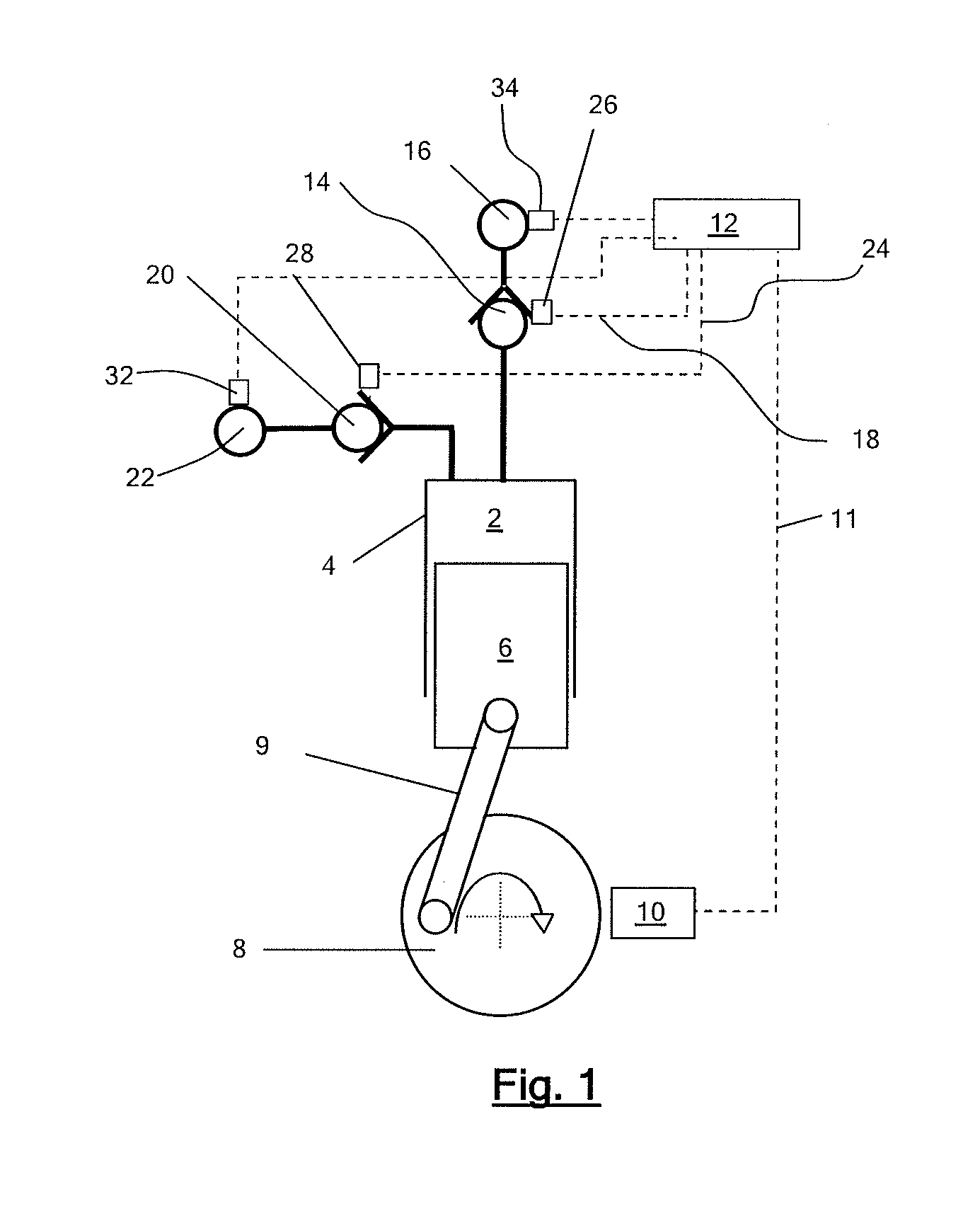
[0105]In a first example, a fluid working machine in the form of a hydraulic pump includes a plurality of working chambers. FIG. 1 illustrates an individual working chamber 2 which has a volume defined by the interior surface of a cylinder 4 and a piston 6 which is driven from a crankshaft 8 by a crank mechanism 9 and which reciprocates within the cylinder to cyclically vary the volume of the working chamber. A shaft position and speed sensor 10 determines the instantaneous angular position and speed of rotation of the shaft, and informs a controller 12, by way of electrical connection 11, which enables the controller to determine the instantaneous phase of the cycles of each individual working chamber. The controller is typically a microprocessor or microcontroller which executes a stored program in use.

[0106]The working chamber comprises a low pressure valve (LPV) in the form of an electronically actuatable face-sealing poppet valve 14, which faces inwards toward the working chamb...


PUM

PropertyMeasurementUnit
junction voltageaaaaaaaaaa
voltageaaaaaaaaaa
volumeaaaaaaaaaa

Abstract

A fluid-working machine has a working chamber of cyclically varying volume, high and low pressure manifolds, and high and low pressure valves for regulating the flow of fluid between the working chamber and the high and low pressure manifolds respectively. A controller actively controls at least one said valve to determine the net displacement of working fluid of the working chamber on a cycle by cycle basis. At least one said valve is a variable timing valve and the controller causes the valve to open or close at a time determined taking into account one or more properties of the performance of the fluid working machine measured during an earlier cycle of working chamber volume.

Description

FIELD OF THE INVENTION [0001]The invention relates to fluid working machines which comprise at least one working chamber of cyclically varying volume in which the net displacement of fluid through the or each working chamber is regulated by at least one electronically controllable valve, on a cycle by cycle basis. The invention aims to facilitate the accurate and efficient operation of fluid working machines of this type.BACKGROUND TO THE INVENTION [0002]Fluid working machines include fluid-driven and / or fluid-driving machines, such as pumps, motors, and machines which can function as either a pump or as a motor in different operating modes.[0003]When a fluid working machine operates as a pump, a low pressure manifold typically acts as a net source of fluid and a high pressure manifold typically acts as a net sink for fluid. When a fluid working machine operates as a motor, a high pressure manifold typically acts as a net source of fluid and a low pressure manifold typically acts as...

Claims


Application Information

Patent Timeline
Patent Type & Authority Applications(United States)
IPC IPC(8): F04B49/00B23P15/00
CPCF04B49/22Y10T29/49236F04B51/00F04B7/00F04B49/06F04B53/10F16K31/48
Inventor RAMPEN, WILLIAM HUGH SALVINSTEIN, UWE BERNHARD PASCALCALDWELL, NIALL JAMESLAIRD, STEPHEN MICHAELJOLY, PIERRE ROBERTFIELDING, MICHAEL RICHARDDUMNOV, DANIIL SERGEEVICH
Owner ARTEMIS INTELLIGENT POWER
Why Eureka
Try Eureka