
Power transmitting apparatuses

a technology of power transmission apparatus and power transmission device, which is applied in the direction of electric control, gearing, road transportation, etc., can solve the problems of disadvantageous increase of the manufacturing cost of the power transmission apparatus, disadvantageous deterioration of fuel economy, etc., and achieve the effect of improving fuel consumption

Active Publication Date: 2012-03-15
FCC KK
View PDF7 Cites 18 Cited by
  • Summary
  • Abstract
  • Description
  • Claims
  • Application Information

AI Technical Summary

Benefits of technology

[0008]An aspect of at least one of the inventions disclosed herein includes the realization that a power transmitting apparatus for a vehicle with a torque converter and an idle-stop mechanism can be configured to improve fuel consumption by avoiding cancellation of fuel-cut-off during vehicle speed reduction without adding an electrically-driven oil pump.
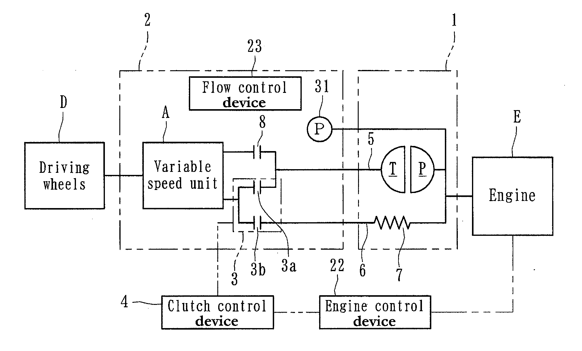
[0020]In some embodiments wherein the power transmitting apparatus further comprises a flow control device configured to limit or prevent the supply of oil to the torque converter by the oil pump and to prioritize the supply of oil to the clutch mechanism and the continuously variable transmission when the vehicle speed is reduced below a predetermined value with fuel being cut off by the engine control device during vehicle speed reduction, it is possible in a power transmitting apparatus for a vehicle mounted with a torque converter and an idle-stop mechanism to improve fuel economy without cancelling the fuel-cut-off during vehicle speed reduction and to reduce the manufacturing cost by eliminating an electrically driven oil pump.
[0022]In some embodiments where the valve is normally urged in a direction for closing the first supply path, the supply of oil to the torque converter can be reliably limited or prevented regardless of the response of the valve when the vehicle speed is reduced below a predetermined value with fuel to the engine being cut off during the vehicle speed reduction.
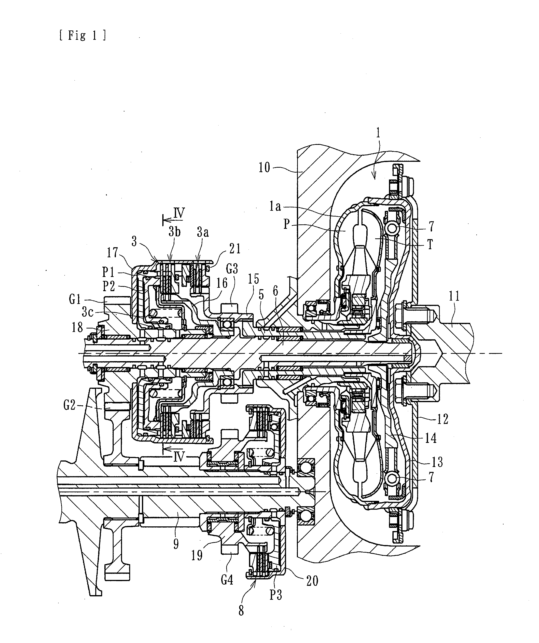
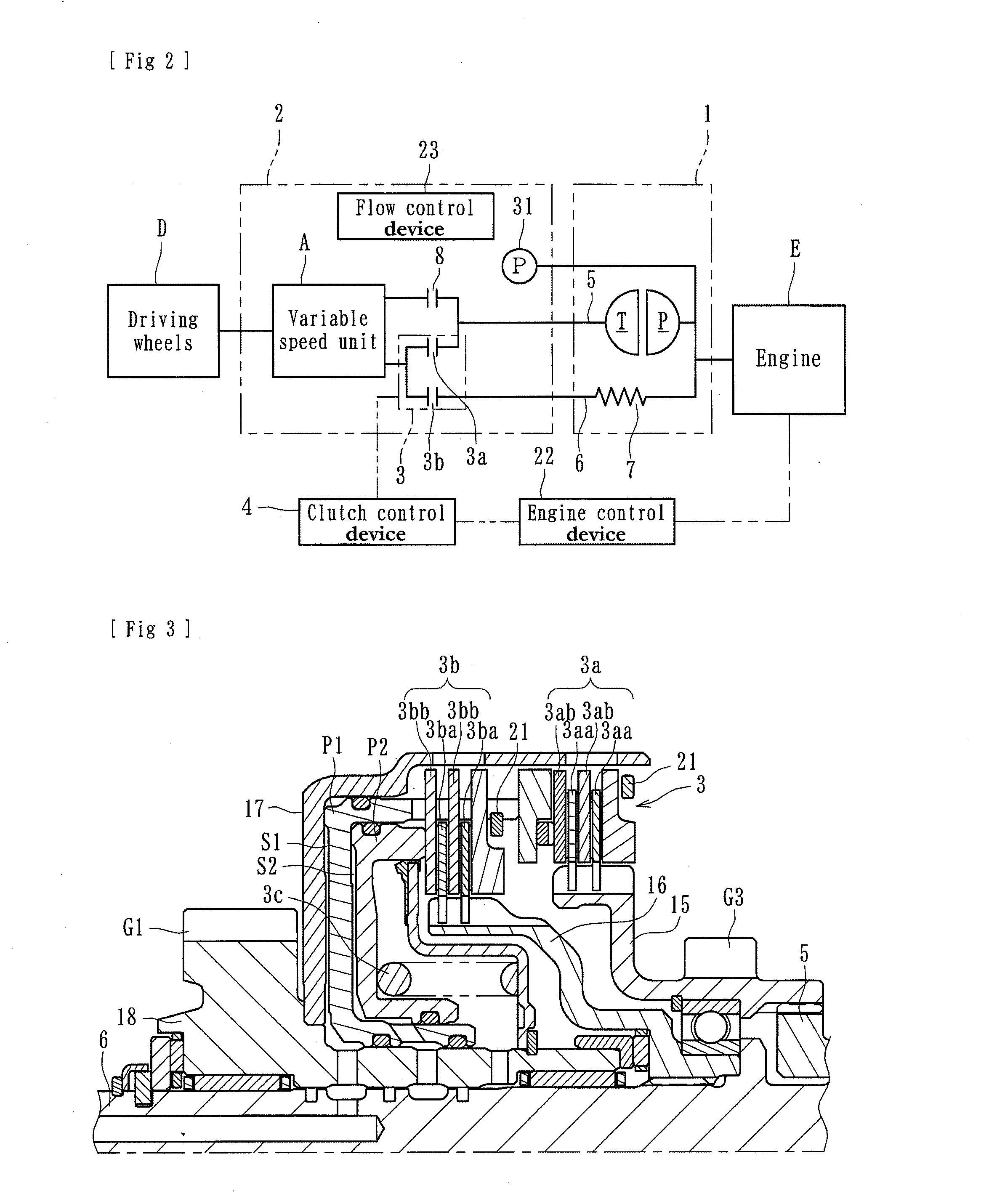
[0024]In some embodiments wherein the clutch mechanism comprises a first clutch device operated during forward vehicle operation and configured to transmit the driving power of the engine to the driving wheels via the power transmitting system of the torque converter and a second clutch device operated during forward vehicle operation and configured to transmit the driving power of the engine to the driving wheels without the power transmitting system of the torque converter, and the clutch control device is configured to selectively operate the first clutch device and the second clutch device in accordance with the vehicle condition to position them in either the first power transmitting condition or the second power transmitting condition, it is possible to avoid complication and increases in size of the power transmitting apparatus, to improve the starting performance due to the torque amplifying function of the torque converter, and to improve the power transmitting efficiency during the steady running of a vehicle. In embodiments where the clutch control device is also configured to operate only the second clutch device when the vehicle speed is reduced below a predetermined value with fuel to the engine being cut off during vehicle speed reduction, oil can be more reliably and smoothly supplied.
[0025]In some embodiments wherein the power transmitting apparatus further comprises a first driving shaft connected to the first clutch device and configured to be rotated by the driving power of the engine via the power transmitting system of the torque converter, and a second driving shaft connected to the second clutch device and configured to be rotated by the driving power of the engine without the power transmitting system of the torque converter, and the first and second driving shafts are arranged coaxially with each other, it is possible to reduce the whole size of the power transmitting apparatus as compared with the size of a power transmitting apparatus in which the first and second driving shafts extend linearly from each other.
[0026]In some embodiments wherein the clutch mechanism comprises a forward operation clutch device operated during forward vehicle operation and configured to transmit the driving power of the engine to the driving wheels via the power transmitting system of the torque converter and a lockup clutch device configured to transmit the driving power of the engine to the driving wheels without the power transmitting system of the torque converter, and the clutch control device is configured to selectively operate the forward-operation clutch device and the lockup clutch device in accordance with the vehicle condition to position them in either the first power transmitting condition or the second power transmitting condition, it is possible to easily apply such a power transmitting apparatus to a vehicle mounted with a lockup clutch device being comparatively in wide use.

Problems solved by technology

In the power transmitting apparatus of the prior art, when the transmission ratio (effective gear ratio) of a CVT must be changed (e.g., to a lower transmission ratio (larger number ratio) in preparation for the next initiation of movement) and vehicle speed has been reduced below a predetermined value because fuel has been cut off from an engine during vehicle speed reduction, then engine speed (RPM) must be temporally increased by cancelling the fuel-cut-off (i.e. resuming of fuel injection), which disadvantageously deteriorates fuel economy.
Although it is possible to change the transmission ratio of the CVT during vehicle operation regardless of the engine speed (or speed of vehicle) without canceling fuel cutoff by providing with an electrically-driven oil pump separate from the engine-driven oil pump, this would disadvantageously increase of the manufacturing cost of the power transmitting apparatus due to the addition of the electrically-driven oil pump.

Method used


Image

  • Power transmitting apparatuses
  • Power transmitting apparatuses
  • Power transmitting apparatuses

Examples


second embodiment

[0089]In this second embodiment, an accumulator 33 can be operatively positioned on an oil supply path of the clutch mechanism 3 from the oil pump 31 as shown in FIG. 15. The accumulator 33 can be configured to accumulate the oil and can be configured so that the oil accumulated in the accumulator 33 is discharged therefrom to the clutch mechanism 3 (second clutch device 3b in this embodiment) and the continuously variable transmission (CVT) 25 when the vehicle speed is reduced below a predetermined value (second vehicle speed Vb) with fuel to the engine E being cut off during vehicle speed reduction. The provision of the accumulator 33 enables the oil supply to the clutch mechanism 3 and the CVT 25 to be more reliable and smooth. A reference numeral 34 in FIG. 15 denotes a check valve.

[0090]The timing of discharging the oil accumulated in the accumulator 33 is not limited only to that at which the vehicle speed is reduced to a predetermined value (second vehicle speed Vb) but also ...

third embodiment

[0094]The lockup clutch device 3′b can be arranged within the torque converter 1 and can be configured to be connected to the turbine T of the torque converter 1 so that the torque converter cover and the turbine are directly connected via a clutch piston. The power transmitting apparatus of this third embodiment can be easily applied to a vehicle mounted with a lockup clutch device (lockup clutch) being comparatively in wide use.

[0095]The power transmitting apparatus of the present inventions have been described with reference to exemplifying embodiments. However, the present inventions are not limited to these illustrated embodiments and the clutch devices can be formed in other configurations.


PUM


Abstract

A power transmitting apparatus for a vehicle mounted with a torque converter and an idle-stop mechanism can be configured to improve fuel economy without cancelling a fuel-cut-ff during vehicle speed reduction and to reduce the manufacturing cost by eliminating an electrically-driven oil pump. A power transmitting apparatus can comprise a torque converter, a clutch mechanism, an oil pump, a continuously variable transmission, a clutch control device, an engine control device, and a flow control device. The flow control device can be configured to limit or prevent the supply of oil to the torque converter by the oil pump and to prioritize the supply of oil to the clutch mechanism and the continuously variable transmission when the vehicle speed is reduced below a predetermined value with fuel being cut off by the engine control device during vehicle speed reduction.

Description

CROSS-REFERENCE TO RELATED APPLICATIONS[0001]This application is a continuation of PCT Application No. PCT / JP2010 / 054513, filed on Mar. 17, 2010, which claims priority to Japanese Application No. 2009066747, filed on Mar. 18, 2009, the entire contents of each of which are hereby incorporated by reference.BACKGROUND OF THE INVENTIONS[0002]1. Field of the Inventions[0003]The present inventions relate to power transmitting apparatuses, such as vehicle transmissions, which transmit power from an engine of a vehicle to the wheels of the vehicle and which are configured to properly select transmission of power and cutting-off of power to or from the wheels.[0004]2. Description of the Related Art[0005]Two types of known power transmitting apparatuses for vehicles (e.g., “automatic transmissions”) provide starting power (power for initiating movement of the vehicle from a stop) in different ways. One type uses a torque converter (“torque converter type”) and another type uses a starting clu...

Claims


Application Information

Patent Timeline
IPC IPC(8): B60W30/18B60W10/10B60W10/02B60W10/04
CPCB60W10/023Y10T477/6197B60W30/18018B60W30/18072B60W2510/0623B60W2520/10F02D29/02F02D41/123F02N11/0814F16H45/02F16H61/0021F16H61/64F16H61/66272F16H2037/023F16H2045/005F16H2061/6608F16H2312/14Y02T10/76Y02T10/48Y10T477/633Y10T477/679Y10T477/753Y10T477/86Y10T477/6403B60W10/06Y02T10/40Y02T10/60
Inventor OHASHI, TATSUYUKIASATSUKE, SHOUJIOISHI, AKIOCHIBA, RYOUHEIISHIMURA, JUNISHIKAWA, KEIICHI
Owner FCC KK
Learn More