Methods and Apparatus for Enhanced Gas Distribution

a gas distribution and gas technology, applied in the direction of gas-gas reaction process, other chemical processes, separation processes, etc., can solve the problems of unfavorable gas distribution, unfavorable gas distribution, and high capital cost of cstrs

Active Publication Date: 2012-03-22
ALPEK POLYESTER SA DE CV
View PDF14 Cites 24 Cited by
  • Summary
  • Abstract
  • Description
  • Claims
  • Application Information

AI Technical Summary

Benefits of technology

[0011]One embodiment of the present invention concerns a reactor defining a reaction zone therein. The reactor of this embodiment comprises a sparger disposed in the reaction zone for introducing fluid into the reaction zone. The sparger of this embodiment comprises at least three radially-extending fluid distribution conduits, where each fluid distribution conduit defines at least three fluid discharge openings, where the radial spacing of the fluid discharge openings associated with each of the fluid distribution conduits decreases outwardly, and where the sparger has a maximum diameter that is at least 90 percent of the diameter of the reaction zone at the elevation where the sparger is disposed.
[0012]Another embodiment of the present invention concerns a reactor defining a reaction zone therein. The reactor of this embodiment comprises a sparger disposed in the reaction zone for introducing fluid into the reaction zone, where the sparger comprises one or more fluid distribution conduits defining in the range of from 20 to 300 fluid discharge openings, where when the sparger is theoretically partitioned into four annular regions of equal area, the cumulative discharge opening area of the fluid discharge openings located in one of the annular regions is within 25 percent of the cumulative discharge opening area of the fluid discharge openings located in at least one other of the annular regions, where the sparger has a total flow-through open area of at least 25 percent, where the fluid discharge openings have an average mean diameter in the range of from about 0.5 to about 2.0 mm, where greater than 50 percent of the fluid discharge openings are positioned to discharge the fluid in a normally downward direction, where the sparger has a maximum diameter in the range of from about 0.5 to about 6 meters, and where the sparger has a maximum diameter that is at least 90 percent of the diameter of the reaction zone at the elevation where the sparger is disposed.
[0013]Yet another embodiment of the present invention concerns a system for at least partially oxidizing an oxidizable compound by contacting at least a portion of the oxidizable compound with a gas-phase oxidant. The system of this embodiment comprises a first oxidation reactor; a second oxidation reactor in downstream fluid-flow communication with the first oxidation reactor; a bubble column reactor in downstream fluid-flow communication with the second oxidation reactor and defining a reaction zone; and a sparger disposed within the reaction zone and configured to discharge at least a portion of the gas-phase oxidant into the reaction zone. In this embodiment, the sparger comprises one or more fluid distribution conduits defining a plurality of fluid discharge openings. Also, when the sparger is theoretically partitioned into four annular regions of equal area, the cumulative discharge opening area of the fluid discharge openings located in one of the annular regions is within 25 percent of the cumulative discharge opening area of the fluid discharge openings located in at least one other of the annular regions. Further, the sparger has a total flow-through open area of at least 25 percent and has a maximum diameter that is at least 90 percent of the diameter of the reaction zone at the elevation where the sparger is disposed.
[0014]Still another embodiment of the present invention concerns a method for producing a dicarboxylic acid. The method of this embodiment comprises (a) contacting an oxidizable compound with a first gas-phase oxidant thereby forming a crude dicarboxylic acid slurry; (b) purifying at least a portion of the crude dicarboxylic acid slurry thereby forming a purified dicarboxylic acid slurry; and (c) contacting at least a portion of the purified dicarboxylic acid slurry with a second gas-phase oxidant in a reaction zone of a bubble column reactor, wherein at least a portion of the second gas-phase oxidant is introduced into the reaction zone via a sparger disposed in the reaction zone. The sparger of this embodiment comprises one or more fluid distribution conduits defining a plurality of fluid discharge openings, where when the sparger is theoretically partitioned into four annular regions of equal area, the cumulative discharge opening area of the fluid discharge openings located in one of the annular regions is within 25 percent of the cumulative discharge opening area of the fluid discharge openings located in at least one other of the annular regions, where the sparger has a total flow-through open area of at least 25 percent, where the sparger has a maximum diameter that is at least 90 percent of the diameter of the reaction zone at the elevation where the sparger is disposed.

Problems solved by technology

If the liquid phase of the multi-phase reaction medium contains an insufficient concentration of molecular oxygen (i.e., if certain portions of the reaction medium are “oxygen-starved”), undesirable side-reactions can generate impurities and / or the intended reactions can be retarded in rate.
If the liquid phase of the reaction medium contains too little of the oxidizable compound, the rate of reaction may be undesirably slow.
Further, if the liquid phase of the reaction medium contains an excess concentration of the oxidizable compound, additional undesirable side-reactions can generate impurities.
For example, CSTRs have a relatively high capital cost due to their requirement for expensive motors, fluid-sealed bearings and drive shafts, and / or complex stirring mechanisms.
Further, the rotating and / or oscillating mechanical components of conventional CSTRs require regular maintenance.
The labor and shutdown time associated with such maintenance adds to the operating cost of CSTRs.
However, even with regular maintenance, the mechanical agitation systems employed in CSTRs are prone to mechanical failure and may require replacement over relatively short periods of time.
CTA contains relatively high levels of impurities (e.g., 4-carboxybenzaldehyde, para-toluic acid, fluorenones, and other color bodies) that render it unsuitable as a feedstock for the production of PET.

Method used


Image

  • Methods and Apparatus for Enhanced Gas Distribution
  • Methods and Apparatus for Enhanced Gas Distribution
  • Methods and Apparatus for Enhanced Gas Distribution

Examples


Embodiment Construction

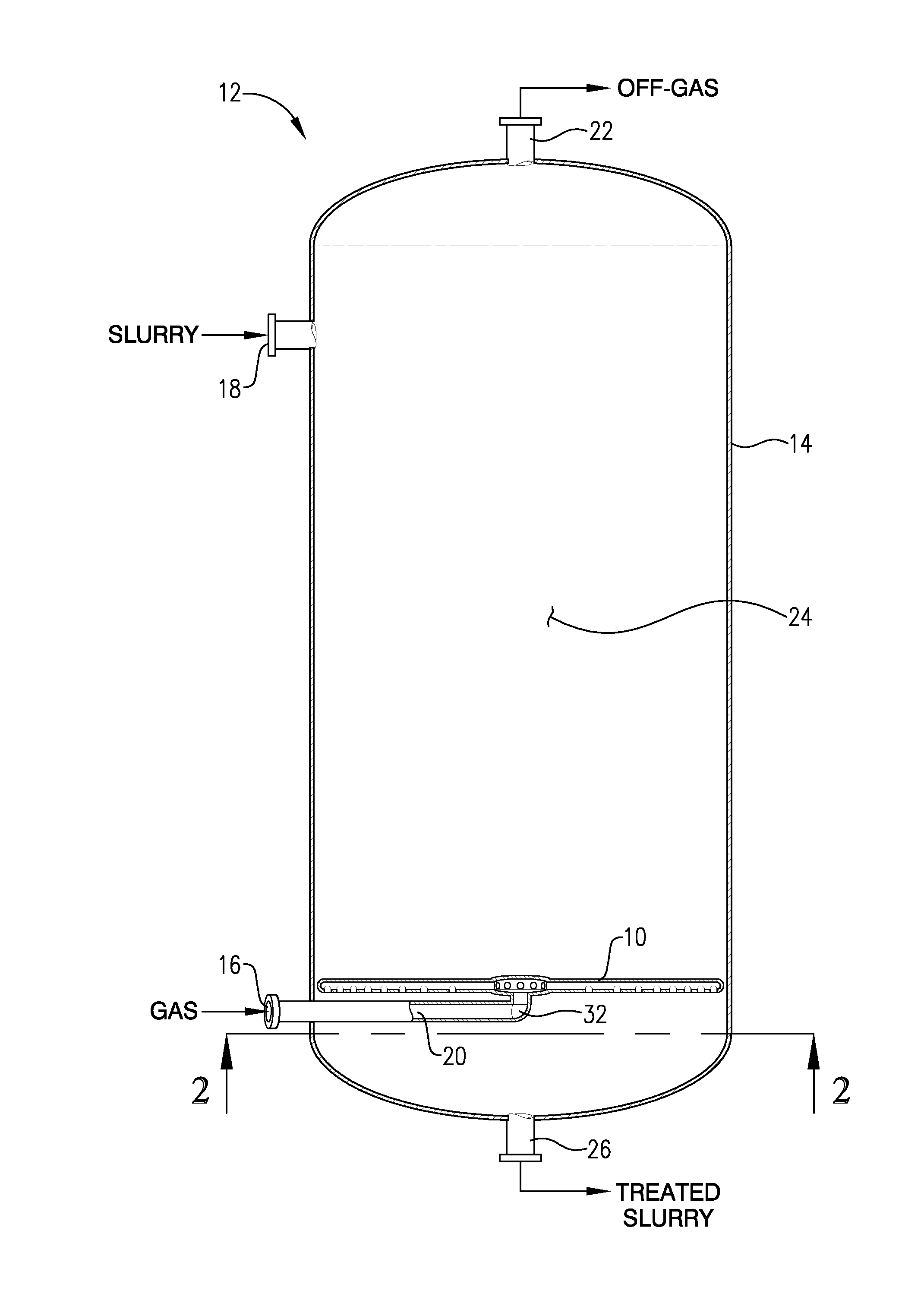
[0023]Various embodiments of the invention concern a sparger for introducing a fluid into the reaction zone of a reactor, such as a bubble column reactor. Such a sparger can be employed in a system for the liquid-phase oxidation of an oxidizable compound, which can be carried out in the liquid phase of a multi-phase reaction medium contained in one or more agitated reactors. Suitable agitated reactors include, for example, bubble-agitated reactors (e.g., bubble column reactors), mechanically agitated reactors (e.g., continuous stirred tank reactors), and flow agitated reactors (e.g., jet reactors).

[0024]Referring initially to FIG. 1, a sparger 10 is shown disposed in a bubble column reactor 12. As used herein, the term “bubble column reactor” shall denote a reactor for facilitating chemical reactions in a multi-phase reaction medium, where agitation of the reaction medium is provided primarily by the upward movement of gas bubbles through the reaction medium. As used herein, the ter...


PUM

PropertyMeasurementUnit
average mean diameteraaaaaaaaaa
diameteraaaaaaaaaa
diameteraaaaaaaaaa

Abstract

Methods and apparatus for introducing a gas into the reaction zone of a reactor. Such methods and apparatus can more evenly distribute the gas throughout the reaction zone. Spargers for introducing a gas into the reaction zone of a reactor can be employed in systems and methods for carrying out the liquid-phase oxidation of an oxidizable compound, such as para-xylene.

Description

BACKGROUND[0001]1. Field of the Invention[0002]Various embodiments of the present invention generally relate to methods and apparatus for enhancing gas distribution in a reactor. More particularly, various embodiments of the present invention relate to spargers providing improved gas distribution in bubble column reactors.[0003]2. Description of the Related Art[0004]Liquid-phase oxidation reactions are employed in a variety of existing commercial processes. For example, liquid-phase oxidation is currently used for the oxidation of aldehydes to acids (e.g., propionaldehyde to propionic acid), the oxidation of cyclohexane to adipic acid, and the oxidation of alkyl aromatics to alcohols, acids, or diacids. A particularly significant commercial oxidation process in the latter category (oxidation of alkyl aromatics) is the liquid-phase catalytic partial oxidation of para-xylene to terephthalic acid. Terephthalic acid is an important compound with a variety of applications. The primary us...

Claims


Application Information

Patent Timeline
Patent Type & Authority Applications(United States)
IPC IPC(8): B01J8/00C09K3/00B01J19/00B01F33/40
CPCB01J4/004B01J19/245B01J19/1818B01J10/002B01J2208/00911B01J8/00B01J10/00B01J19/24B01F23/20B01J8/1827B01J8/22
Inventor SHAIKH, ASHFAQ
Owner ALPEK POLYESTER SA DE CV
Why Eureka
Try Eureka