Oscillator

a technology of oscillator and oscillator plate, which is applied in the direction of oscillator generator, electrical apparatus, etc., can solve the problems of phase noise floor degradation of the oscillator output, reduce the number of layers to be formed in the coil forming process, reduce the area necessary for the coil to be placed, and reduce the production cost

Inactive Publication Date: 2012-03-22
NIHON DEMPA KOGYO CO LTD
View PDF2 Cites 19 Cited by
  • Summary
  • Abstract
  • Description
  • Claims
  • Application Information

AI Technical Summary

Benefits of technology

[0030]Further, in the present invention, the above oscillator is configured such that the first coil and the second coil are placed in parallel with each other in a horizontal direction with respect to the substrate. With the configuration, the present invention yields such an effect that the number of layers to be formed in a coil forming process can be reduced, thereby reducing production cost.
[0031]Furthermore, in the pr

Problems solved by technology

However, the oscillators using a conventional MEMS resonator have such a problem that since an oscillation output is extracted from a

Method used


Image

  • Oscillator
  • Oscillator
  • Oscillator

Examples


first embodiment

Effect of First Embodiment

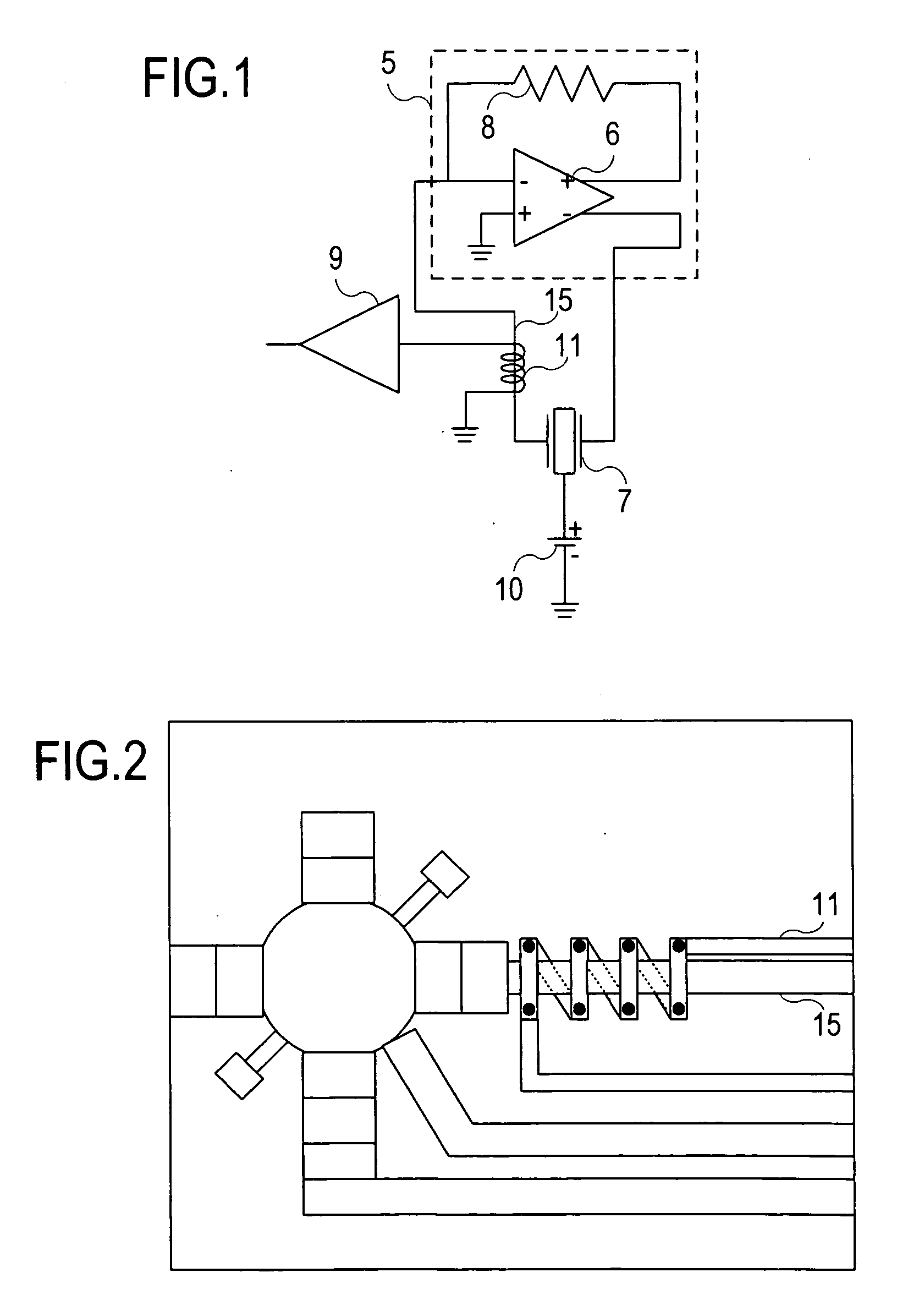
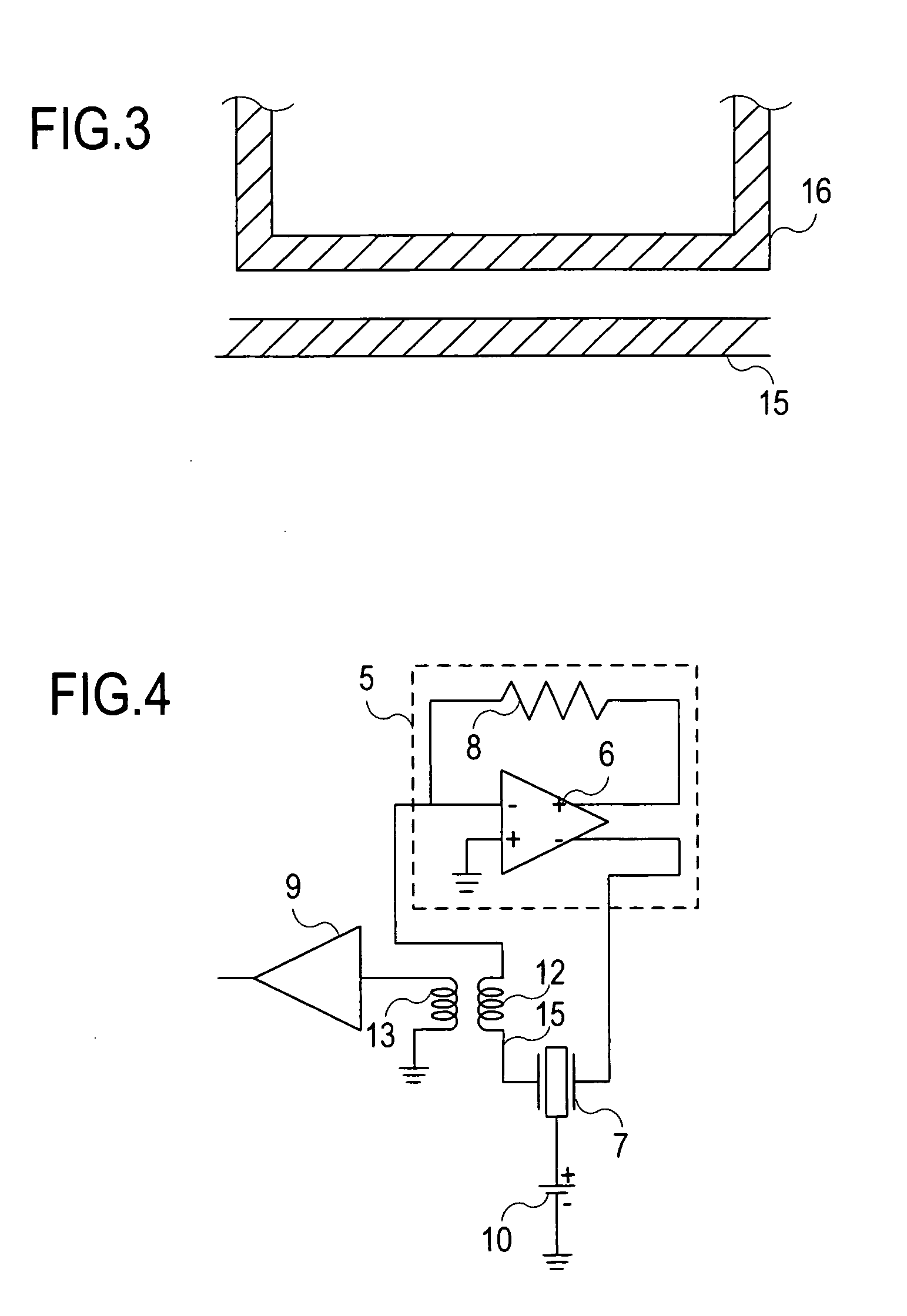
[0057]In accordance with the oscillator according to the first embodiment of the present invention, the oscillator including the MEMS resonator 7, the TIA 5, and the buffer amplifier 9 further includes the oscillation output coil 11 in which one end is connected to ground and the other end is connected to the buffer amplifier 9, which oscillation output coil 11 is provided so as to surround in a noncontact manner the wiring line 15 that connects the MEMS resonator 7 with a TIA-input side. In this configuration, the oscillation output coil 11 couples with the wiring line 15 by electromagnetic induction, thereby converting a current to a voltage and supplying it to the buffer amplifier 9. As such, an oscillator output can be extracted not from a TIA-output side but from the oscillation output coil 11, thereby yielding such an effect that an influence of the floor noise of the TIA can be reduced and phase noise characteristics of the oscillator output can be i...

second embodiment

Effect of Second Embodiment

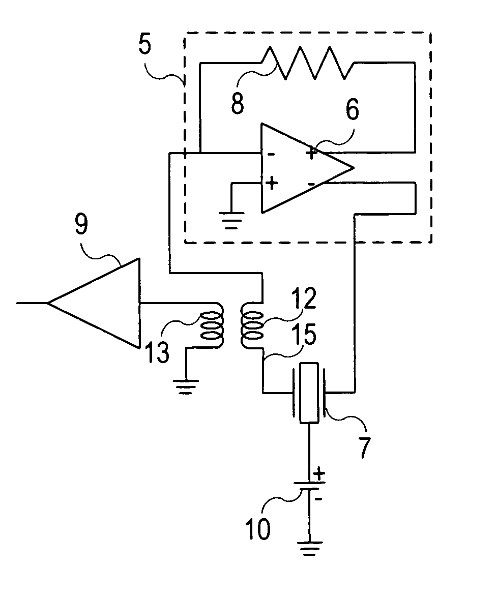
[0075]In accordance with the oscillator according to the second embodiment of the present invention, the oscillator including the MEMS resonator 7, the TIA 5, and the buffer amplifier 9 further includes the TIA-input-side coil 12 provided in series to the wiring line 15 that connects the MEMS resonator 7 with the TIA-input side, and the oscillation-output-side coil 13 in which one end is connected to ground and the other end is connected to the buffer amplifier 9, which oscillation-output-side coil 13 is provided opposed to the TIA-input-side coil 12. In the oscillator, the TIA-input-side coil 12 and the oscillation-output-side coil 13 form a transformer so as to convert a current to a voltage and supply the voltage to the buffer amplifier 9. Thus, an oscillator output can be extracted not from the TIA-output side but from the oscillation-output-side coil 13. As a result, such effects can be obtained that an influence of the floor noise of the TIA is reduc...


PUM


Abstract

Provided is an oscillator using an MEMS resonator, which can reduce an influence of noise of a TIA and improve phase noise characteristics of an oscillator output. The oscillator includes an MEMS resonator, a TIA, a buffer amplifier, and a current/voltage converter that couples, by electromagnetic induction, with a wiring line via which an output of the MEMS resonator is fed to the TIA, so as to convert a current flowing in the wiring line to a voltage and output the voltage to the buffer amplifier. Thus, the oscillator output is extracted from the current/voltage converter. Further, the current/voltage converter is provided in the form of an oscillation output coil provided so as to surround the wiring line in a noncontact manner, in which oscillation output coil one end is connected to ground and the other end is connected to the buffer amplifier.

Description

[0001]This application has a priority of Japanese no. 2010-212855 filed Sep. 22, 2010, hereby incorporated by reference.BACKGROUND OF THE INVENTION[0002]1. Field of the Invention[0003]The present invention relates to an oscillator, especially an oscillator that can improve phase noise characteristics.[0004]2. Description of the Related ArtDESCRIPTION OF THE PRIOR ART[0005]As a conventional oscillator, there has been an oscillator that uses a resonator having a relatively large equivalent series resistance (for example, 500Ω or more). Especially, some MEMS (Micro Electro Mechanical Systems) oscillators use, as an amplifying element for oscillations, a transimpedance amplifier (TIA).[0006]The conventional oscillator is explained below with reference to FIG. 7. FIG. 7 is a circuit diagram illustrating an example of an oscillator using a conventional MEMS resonator.[0007]As illustrated in FIG. 7, the conventional oscillator includes an MEMS resonator 7, a TIA 5, and a buffer amplifier 9...

Claims


Application Information

Patent Timeline
IPC IPC(8): H03B1/04
CPCH03B5/30H03B2200/0088H03B2200/0034
Inventor ASAMURA, FUMIOISHII, TAKEHITO
Owner NIHON DEMPA KOGYO CO LTD
Why Eureka
Try Eureka