Data processing apparatus, control device and data storage device

a data processing apparatus and control device technology, applied in the direction of instruments, coding, code conversion, etc., can solve the problems of insufficient reduction of power consumption, data stored in nonvolatile rams a lot of errors, and more power consumption, so as to achieve small power consumption, small power consumption, the effect of small power consumption

Inactive Publication Date: 2012-03-22
THE UNIV OF TOKYO
View PDF1 Cites 23 Cited by
  • Summary
  • Abstract
  • Description
  • Claims
  • Application Information

AI Technical Summary

Benefits of technology

[0010]In a data processing apparatus reading out program stored in a nonvolatile memory and performing data processing based on the read program, using a NOR type flash memory having comparative high speed in reading out data enables readout speed in reading out the program to be high. However, larger increase in read out speed is desired.
[0040]In the fourth data processing apparatus according to this aspect of the invention, the data processing apparatus controls the resistance memory to read out program stored therein when the readout of the program is requested. In general, a resistance memory reads and writes data faster than NOR type flash memory. Therefore, storing the program in the resistance memory and controlling the resistance memory to read out program stored therein enable to readout the program at a high speed. Thus faster processing of data is accomplished.

Problems solved by technology

The more the number of times of this refresh operation is, the more power consumption is.
Frequent rewrite in data in the nonvolatile RAM causes data stored in the nonvolatile RAM a lot of errors.
Therefore, sufficient decrease of the power consumption is not accomplished.
In a storage device having a nonvolatile storage device such as HDD etc. and a nonvolatile RAM as a cache memory, the more number of rewrite times is, the more deteriorated memory cells configuring a nonvolatile RAM are and the higher possibility of occurrence of data errors is.
It is considered that suppressing error in the nonvolatile RAM is one of important problems.

Method used


Image

  • Data processing apparatus, control device and data storage device
  • Data processing apparatus, control device and data storage device
  • Data processing apparatus, control device and data storage device

Examples


first embodiment

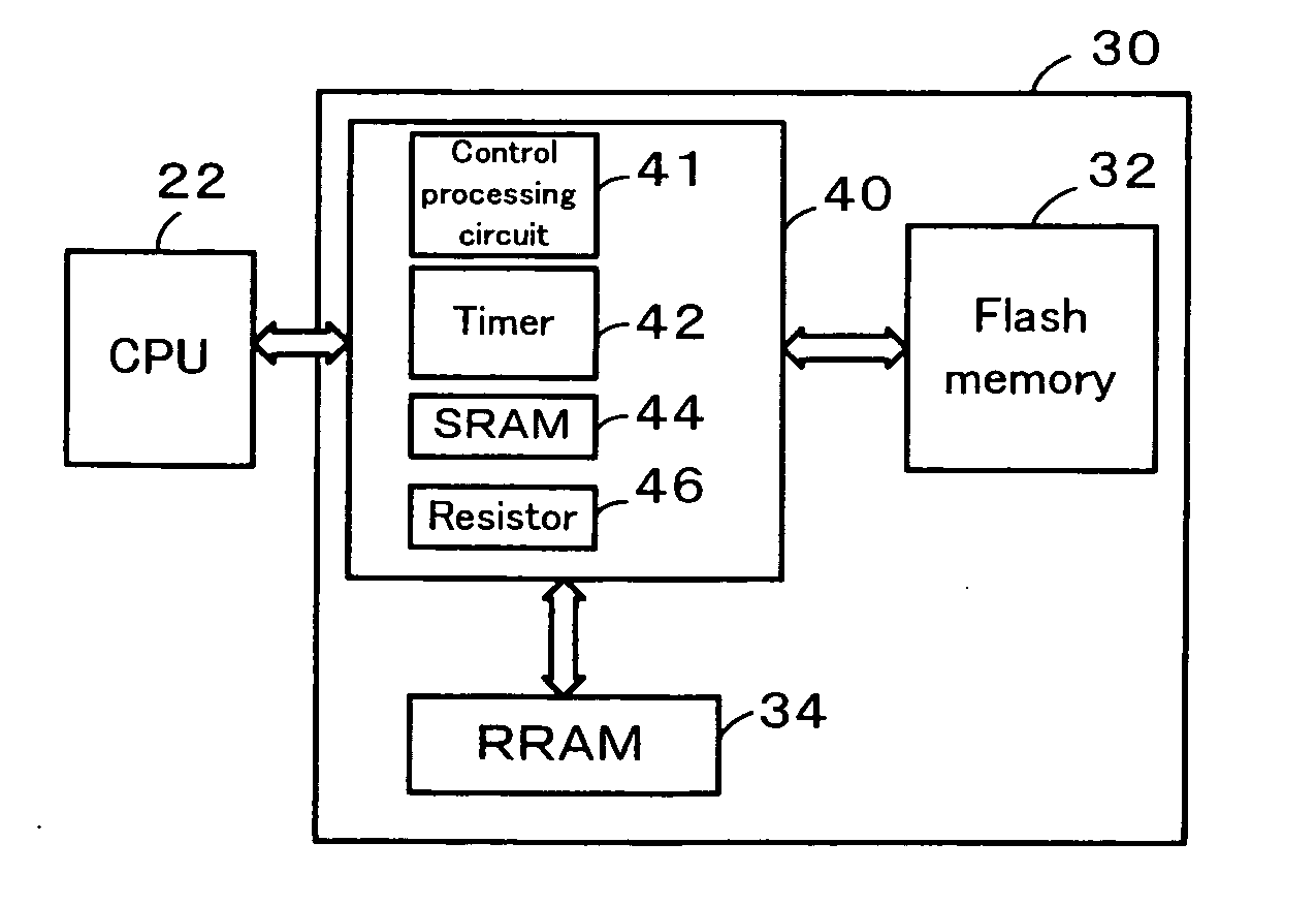
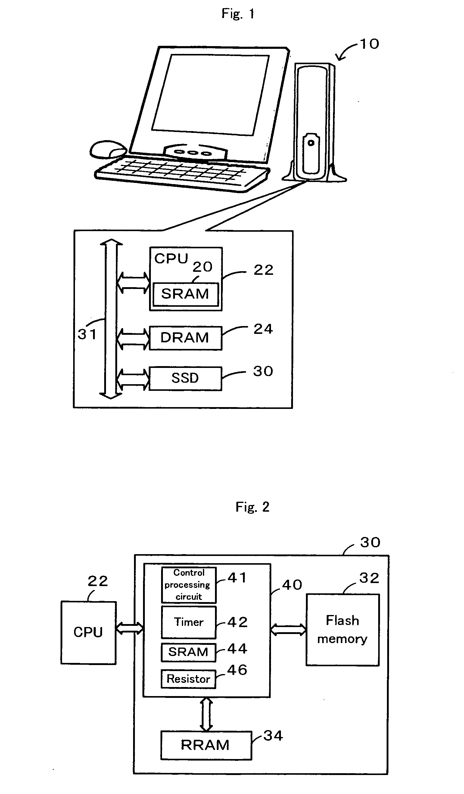
[0070]FIG. 1 schematically illustrates one configuration of a PC 10 that is a data processing apparatus as a FIG. 2 schematically illustrates one configuration of a SSD 30 mounted on the PC 10. The PC 10 is configured to be a personal computer. The PC 10 has: a CPU 22 configured to include a SRAM 20 as a cache memory and to execute arithmetic processing and control as a host device; a DRAM 24 configured to be a main memory storing data temporally; and an SSD 30 configured to be large capacity storage device storing application programs and data. The CPU 22, the DRAM 24 and the SSD 30 transfer data or signal via a bus 31 with one another.

[0071]Application programs or data files are stored in the SSD 30. The CPU 22 controls the SSD 30 and the DRAM 24 to store the application programs or data files stored in the SSD 30. Then, the CPU 22 controls the SSD 30 and the DRAM 24 to execute arithmetic processing based on the application programs stored in the DRAM 24. The CPU 22 also controls...

second embodiment

[0098]FIG. 7 schematically illustrates one configuration of a PC 110 that is a data processing apparatus as a FIG. 8 schematically illustrates one configuration of a SSD 130 mounted on the PC 110. The PC 110 is configured to be a personal computer. The PC 110 has: a CPU122 configured to include a SRAM 120 as a cache memory and to execute arithmetic processing and control as a host device; a DRAM 124 configured to be a main memory storing data temporally; and an SSD 130 configured to be large capacity storage device storing application programs and data. The CPU 122, the DRAM 124 and the SSD 130 transfer data or signal via a bus 131 with one another.

[0099]Application programs or data files are stored in the SSD 130. The CPU 122 controls the SSD 130 and the DRAM 124 to store the application programs or data files stored in the SSD 130. Then, the CPU 122 controls the SSD 130 and the DRAM 124 to execute arithmetic processing based on the application programs stored in the DRAM 124. The...

third embodiment

[0130]FIG. 15 schematically illustrates one configuration of a PC 210 that is a data processing apparatus as a The PC 210 is configured to be a personal computer. The PC 210 has: a CPU 222 configured to include a SRAM 220 as a cache memory and to execute arithmetic processing and control as a host device; a DRAM 224 configured to be a main memory storing data temporally; and an SSD (Solid State Drive) 230 configured to be large capacity storage device storing application programs and data. The CPU 222, the DRAM 224 and the SSD 230 transfer data or signal via a bus 231 with one another.

[0131]Application programs or data files are stored in the SSD 230. The CPU 222 controls the SSD 230 and the DRAM 224 to store the application programs or data files stored in the SSD 230. Then, the CPU 222 controls the SSD 230 and the DRAM 224 to execute arithmetic processing based on the application programs stored in the DRAM 224. The CPU 222 also controls the SSD 230 and the DRAM 224 to store resu...


PUM


Abstract

When write data D is high rewritten data, a PC 10 controls a DRAM 24 to store the write data D (steps S100 and S110). When the write data D is not the high rewritten data, the PC 10 outputs an RRAM write request signal and the write data D to an SSD (step S100 and S120). A memory controller of the SSD input the RRAM write request signal controls the RRAM and an SRAM to store the write data D in the RRAM or the SRAM. This treatment enables data stored in the DRAM to be rewritten frequently. Therefore, the decrease of number of times of refresh operation of the DRAM and the decrease of power consumption are accomplished.

Description

BACKGROUND OF THE INVENTION[0001]1. Field of the Invention[0002]The present invention relates to a data processing apparatus, a control device and a data storage device.[0003]2. Description of the Prior Art[0004]One proposed structure of a control device controls a FeRAM (Ferroelectric Random Access Memory) as a cache memory or HDD to store data from a PC system (see, for example, Non-Patent Document 1). In the structure, the FeRAM is configured as a nonvolatile random access memory maintaining data stored therein when a power supply is stopped. In this device, data in the FeRAM is not regularly needed to be evacuated to HDD in preparation to an unexpected stop power supply. This arrangement enables to increase amount of data stored to FeRAM, and to increase cache hit ratio.[0005]Non-patent document 1: Daisaburo Takahashi et al. “A 128 Mb ChainFeRAMTM and System Designs for HDD Application and Enhanced HDD Performance”, IEEE Asian Solid-State Circuits Conference, Nov. 16-18, 2009, T...

Claims


Application Information

Patent Timeline
Patent Type & Authority Applications(United States)
IPC IPC(8): G06F11/16G06F12/00
CPCG06F1/3203G06F1/3275Y02B60/1228Y02B60/1225Y02B60/1282G06F1/3287G11C11/005G11C13/0002G11C13/0033G11C13/0069Y02D10/00
Inventor TAKEUCHI, KENFUKUDA, MAYUMI
Owner THE UNIV OF TOKYO
Why Eureka
Try Eureka