Electro-optical inspection apparatus and method with dust or particle collection function

a technology of optical inspection and function, applied in the direction of material analysis using wave/particle radiation, instruments, nuclear engineering, etc., can solve the problems of significant deterioration of performance, difficult to reduce dust or particles of very small sizes, and insufficient width of wiring or insulation resistance, etc., to facilitate the detection of short defects and high contrast observation

Inactive Publication Date: 2012-03-29
EBARA CORP
View PDF9 Cites 27 Cited by
  • Summary
  • Abstract
  • Description
  • Claims
  • Application Information

AI Technical Summary

Benefits of technology

[0048]Further, in the electro-optical inspection apparatus according to the invention, it is further preferable to comprise an energy control means for setting energy of the electron beam directing to the sample surface and energy supplied to the sample such that electrons directing from the sample surface to a detector within a transition band which contains mirror electrons and secondary electrons, and an aperture adjustment mechanism for adjusting a location of at least an aperture on a plane perpendicular to an axis of a secondary electro-optical system of the inspection apparatus, so that e...

Problems solved by technology

In a semiconductor or LSI manufacturing process, if the killer defects are on the sample surface, a width of wiring or insulation resistance becomes insufficient so that performance is significantly deteriorated.
However, it is usually difficult to reduce dusts or particles having very small sizes, in particular, of 100 nm or smaller.
Adhesion of dusts or particles generated by an operation of the inspection apparatus to the sample surface has become a critical problem, and it is necessary to take a countermeasure.
However, in the conventional dusts or particle adhesion prevention mechanism, it is difficult to prevent dusts or particles such as fine particles of 100 nm or smaller, for example, from adhering to the sample surface.
Therefore, conventional example described in Patent Document 1 cannot prevent dusts or particles from adhering to the sample surfa...

Method used


Image

  • Electro-optical inspection apparatus and method with dust or particle collection function
  • Electro-optical inspection apparatus and method with dust or particle collection function
  • Electro-optical inspection apparatus and method with dust or particle collection function

Examples


first embodiment

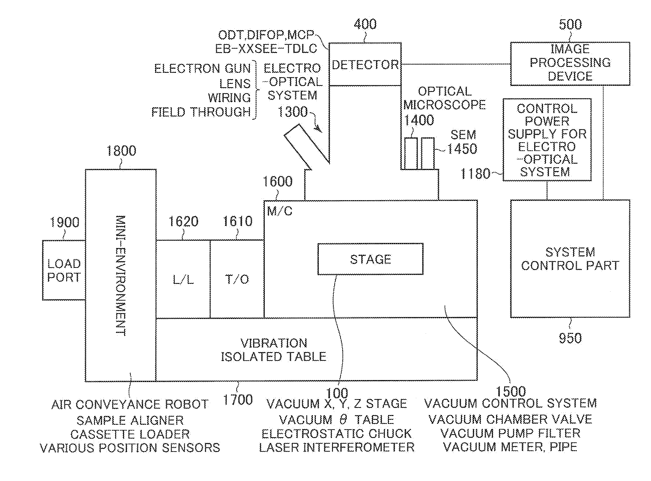
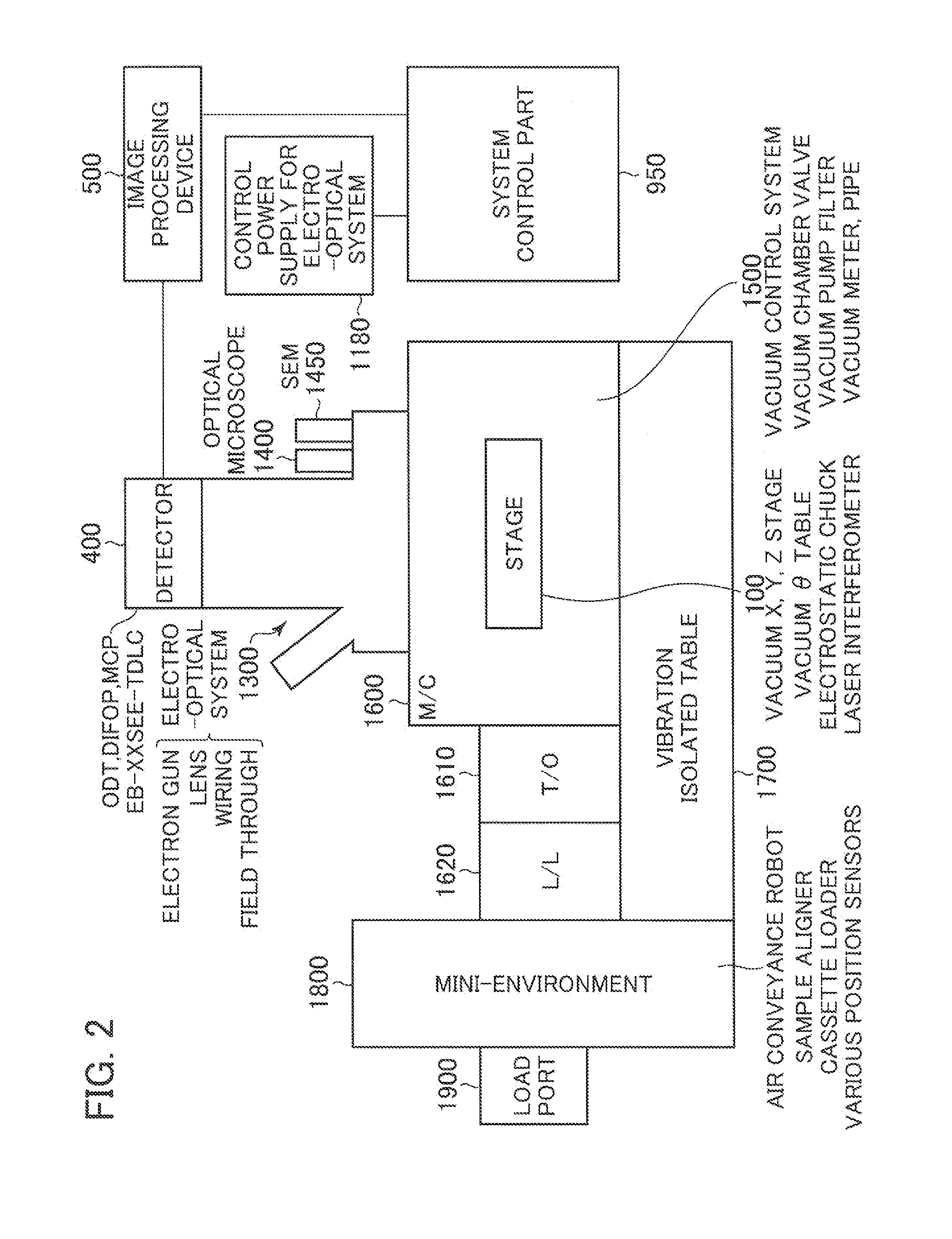
[0172]FIG. 2 is a diagram illustrating a general structural example of a sample observation system (inspection system) of the first embodiment including an electro-optical inspection apparatus according to the present invention. This sample observation system is constituted as a combination type sample observation system capable of observing a sample with the mapping projection type electro-optical system and an optical microscope and of observing a sample with the SEM type electro-optical system.

[0173]The combination type sample observation system illustrated in FIG. 2 includes a load port 1900, a mini-environment 1800, a load lock 1620, a transfer chamber 1610, a main chamber 1600, a mapping projection type electro-optical system 1300, and the image processing device 500. The mini-environment 1800 is provided with an air conveyance robot, a sample alignment device, a clean air supply mechanism, and the like (not shown). In addition, the transfer chamber 1610 that is always in a va...

second embodiment

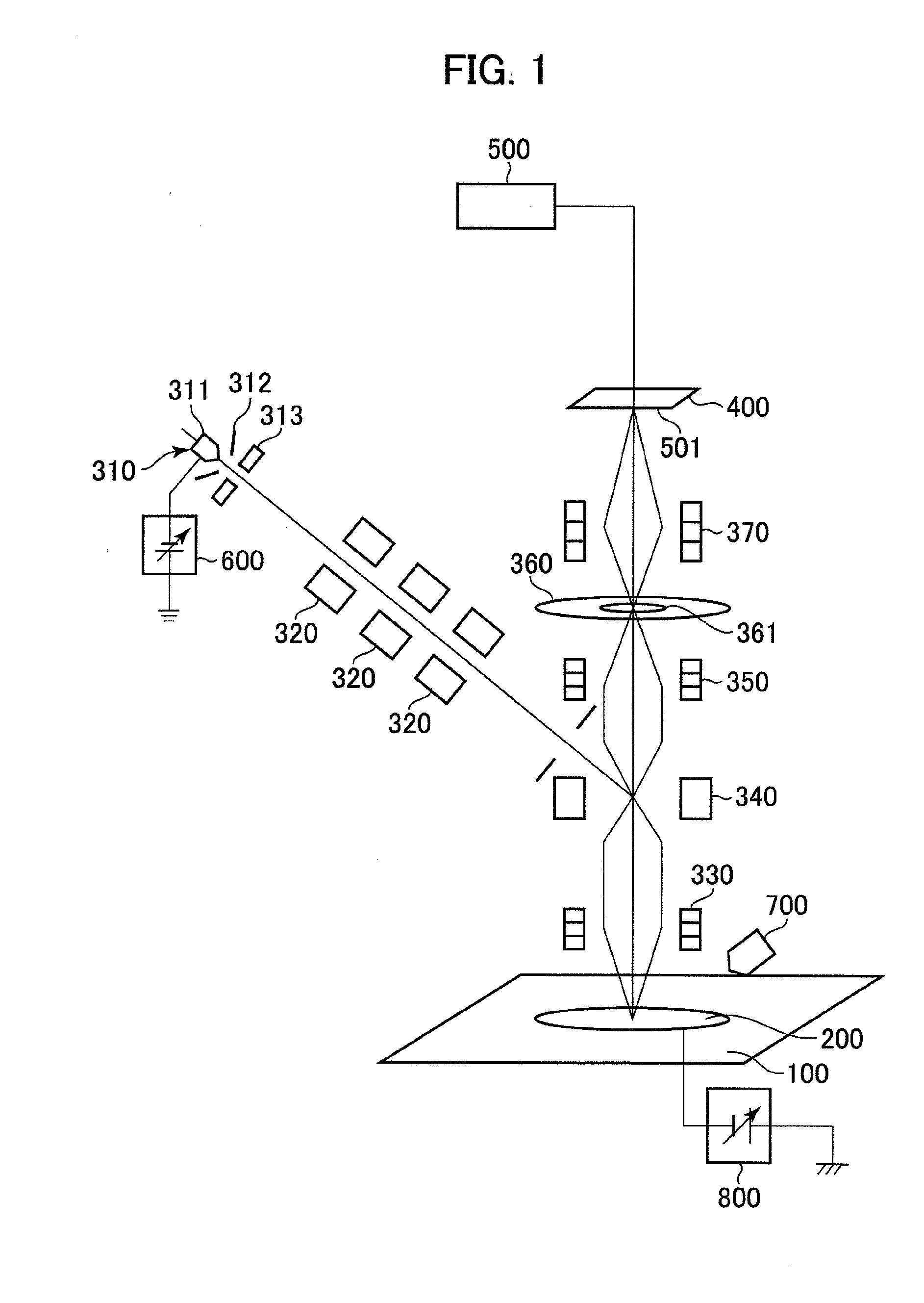
[0306]Although not illustrated in FIG. 33, the electro-optical inspection apparatus of the second embodiment may also include the charged electron beam irradiation means 700 (see FIG. 1) as necessary.

[0307]The electro-optical inspection apparatus illustrated in FIG. 33 is different in structure from the electro-optical inspection apparatus illustrated in FIG. 1 in that the NA adjustment aperture plate 360a includes a movable, multi-selectable NA adjusting aperture moving mechanism. In other words, the NA adjustment aperture plate 360a includes a plurality of types of NA apertures 361 and 362 having different aperture diameters, and the NA apertures 361 and 362 determining the numerical aperture (NA) can be adjusted in position (can be switched) in the plane by the NA aperture moving mechanism (not shown).

[0308]In the electro-optical inspection apparatus illustrated in FIG. 33, the NA adjustment aperture plate 360a has a plurality of NA apertures 361 and 362 having different sizes, a...


PUM


Abstract

An electro-optical inspection apparatus is provided that is capable of preventing adhesion of dust or particles to the sample surface as much as possible. A stage (100) on which a sample (200) is placed is disposed inside a vacuum chamber (112) that can be evacuated to vacuum, and a dust collecting electrode (122) is disposed to surround a periphery of the sample (200). The dust collecting electrode (122) is applied with a voltage having the same polarity as a voltage applied to the sample (200) and an absolute value that is the same or larger than an absolute value of the voltage. Thus, because dust or particles such as particles adhere to the dust collecting electrode (122), adhesion of the dust or particles to the sample surface can be reduced. Instead of using the dust collecting electrode, it is possible to form a recess on a wall of the vacuum chamber containing the stage, or to dispose on the wall a metal plate having a mesh structure to which a predetermined voltage is applied. In addition, adhesion of dust or particles can be further reduced by disposing a gap control plate (124) having a through hole (124a) at the center above the sample (200) and the dust collecting electrode (122).

Description

TECHNICAL FIELD[0001]The present invention relates to an electro-optical inspection apparatus and method for inspecting a sample surface using an electron beam, and more particularly, to an electro-optical inspection apparatus and method that is capable of inspecting a sample surface at high sensitivity using an electron beam while preventing adhesion of dusts or particles to sample surfaces (of front and back sides and peripheral edges).BACKGROUND ART[0002]The electro-optical inspection apparatus is used for obtaining an image of a sample surface of a semiconductor wafer or the like by irradiating the sample surface with a primary electron beam, and detecting secondary electrons or mirror electrons emitted from the sample surface, to perform inspection of defects on the sample surface and / or pattern evaluation of the sample surface on the basis of the obtained image.[0003]In addition, it is known that while a sample such as a semiconductor wafer is conveyed in the air or in vacuum ...

Claims


Application Information

Patent Timeline
IPC IPC(8): G01N23/20G01N23/00
CPCH01J37/265H01J37/29H01J2237/004H01J37/22H01J2237/24495H01J2237/24564H01J2237/2817H01J2237/022H01J37/10H01J37/244H01J37/26
Inventor WATANABE, KENJIHATAKEYAMA, MASAHIRONAITO, YOSHIHIKOKOHAMA, TATSUYATERAO, KENJIMURAKAMI, TAKESHIHAYASHI, TAKEHIDETSUKAMOTO, KIWAMUSOBUKAWA, HIROSHIKIMURA, NORIO
Owner EBARA CORP
Why Eureka
Try Eureka