
Thermally assisted magnetic recording head

a technology of magnetic recording and thermally assisted head, which is applied in the field of head for thermally assisted magnetic recording, can solve the problems of increasing the anisotropic magnetic field (coercive force) of the magnetic recording medium, lowering the thermal stability of the magnetic particle magnetization, and unable to write, so as to achieve the effect of suppressing the degradation of the magnetic pol

Active Publication Date: 2012-03-29
TDK CORPARATION
View PDF6 Cites 16 Cited by
  • Summary
  • Abstract
  • Description
  • Claims
  • Application Information

AI Technical Summary

Benefits of technology

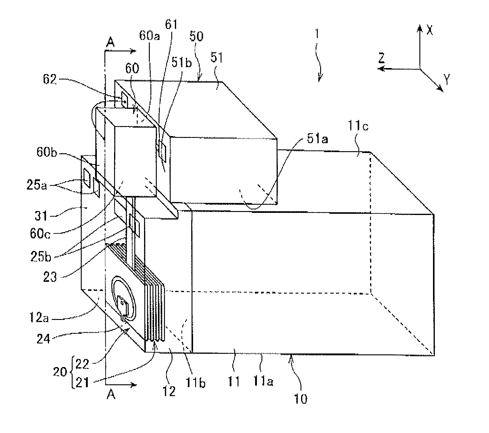
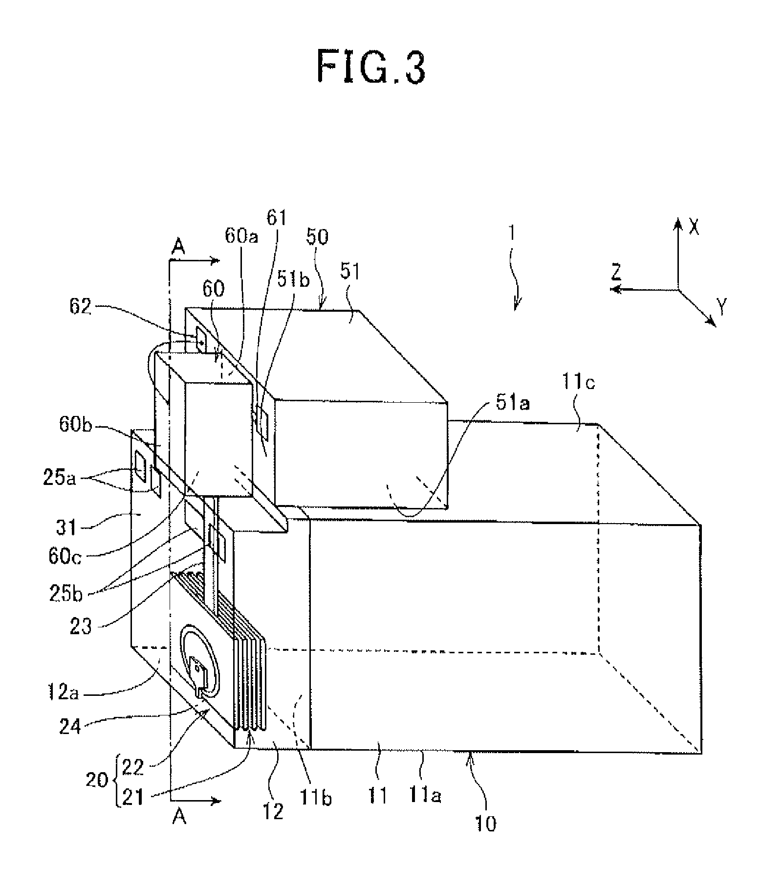
[0012]The present invention has an object to provide a thermally assisted head that can suppress degradation of a magnetic pole by allowing the heat from a near-field light generating portion of a plasmon generator on the side of the magnetic pole.
[0028]According to the present invention, a thermally assisted magnetic recording head is provided that suppresses degradation of the magnetic pole by allowing the heat to escape from the near-field light generating point of the plasmon generator to the side of the magnetic pole.

Problems solved by technology

However, if the size of the magnetic particles is reduced, there is a problem that thermal stability for magnetization of the magnetic particles is lowered as the volume of the magnetic particles is reduced.
However, this increase in Ku causes an increase in anisotropic magnetic field (coercive force) of the magnetic recording medium.
As a result, when the anisotropic magnetic field of the magnetic recording medium exceeds an acceptable value determined from the upper value of the writing magnetic field intensity, writing becomes impossible.
As a result, there are problems that a near-field light generating end surface having the near-field light generating portion of the plasmon generator protrudes on the side of the magnetic recording medium, and that optical-power efficiency of the plasmon generator significantly decreases.
As a result, there is a problem that degradation of the magnetic pole and the like are caused.

Method used


Image

  • Thermally assisted magnetic recording head
  • Thermally assisted magnetic recording head
  • Thermally assisted magnetic recording head

Examples


experimental example 1

[0122]Regarding fluctuations of temperatures at a magnetic pole due to generation of the near-field light in the near-field light generating optical system in the thermally assisted magnetic recording head, a simulation analysis experiment was conducted as discussed below.

[0123]This simulation analysis experiment was conducted using a three-dimensional finite-difference time-domain method (FDTD method) that is a method for electromagnetic field analysis.

[0124]As a thermally assisted magnetic recording head according to the present experimental example, the thermally assisted magnetic recording head 1 shown in FIGS. 7 and 8 was used, in which the waveguide 23 is formed by Ta2O5 (refractive index nWG=2.15) that has a cross-section with a 500 nm width in the Y axis direction and a 400 nm thickness in the Z axis direction, the passivation layer 31 that functions as a cladding is formed by Al2O3 (alumina, refractive index nBF=1.65), and the convex part 222 of the main magnetic pole 220 i...

experimental example 2

[0129]The following simulation analysis experiment was conducted regarding the relationship between the thickness of the plasmon generator and the peak intensity of the near-field light for the generation of the near-field light in the near-field light generating optical system in the thermally assisted magnetic recording head.

[0130]The simulation analysis experiment was conducted using a three-dimensional finite-difference time-domain method (FDTD method) that is a method for electromagnetic field analysis.

[0131]In the present experimental example, the thermally assisted magnetic recording head 1 shown in FIGS. 7 and 8 was used, in which the waveguide 23 was formed by Ta2O5 (refractive index nWG=2.15) that had a cross-section with a 500 nm width in the Y axis direction and a 400 nm thickness in the Z axis direction, the passivation layer 31 that functions as a cladding was formed by Al2O3 (alumina, refractive index nBF=1.65), and the convex part 222 of the main magnetic pole 220 wa...

experimental example 3

[0134]The following simulation analysis experiment was conducted regarding the relationship between the thickness of the plasmon generator and the peak intensity of the near-field light for the generation of the near-field light in the near-field light generating optical system in the thermally assisted magnetic recording head.

[0135]The simulation analysis experiment was conducted using a three-dimensional finite-difference time-domain method (FDTD method) that is a method for electromagnetic field analysis.

[0136]In the present experimental example, the thermally assisted magnetic recording head 1 shown in FIGS. 7 and 8 was used, in which the waveguide 23 was formed by Ta2O5 (refractive index nWG=2.15) that had a cross-section with a 500 nm width in the Y axis direction and a 400 nm thickness in the Z axis direction, the passivation layer 31 that functions as a cladding was formed by Al2O3 (alumina, refractive index nBF=1.65), and the convex part 222 of the main magnetic pole 220 wa...


PUM


Abstract

A thermally assisted magnetic head includes a magnetic pole that generates a writing magnetic field from an air bearing surface (ABS); a waveguide through which light propagates; and a plasmon generator generating near-field light from a near-field light generating end surface by coupling the light thereto in a surface plasmon mode. The magnetic pole includes a convex part protruding in a substantially V-shape along a light propagation direction of the waveguide. The plasmon generator includes a substantially V-shaped part contacting the convex part, and as seen from a side of the ABS, a thickness of the plasmon generator in a direction perpendicular to convex part contacting sides gradually increases from an end in a direction away from the waveguide, the convex part contacting sides being linear sides that form the substantially V-shaped part of the plasmon generator and contacting the convex part.

Description

BACKGROUND OF THE INVENTION[0001]1. Field of the Invention[0002]The present invention relates to a head for a thermally assisted magnetic recording that records data by emitting near-field (NF) light on a magnetic recording medium and by decreasing an anisotropic magnetic field of the magnetic recording medium.[0003]2. Description of the Related Art[0004]In the field of magnetic recording using a head and a medium, further improvements have been demanded in performance of thin film magnetic heads and magnetic recording media in view of an increase in recording density of magnetic disk devices. For the thin film magnetic heads, composite type thin film magnetic heads configured from lamination of a reading magnetoresistive (MR) element and a writing electromagnetic conversion element are being widely used.[0005]The magnetic recording medium is a non-continuous medium, in which magnetic particles are aggregated. Each magnetic particle has a single magnetic domain. In this magnetic rec...

Claims


Application Information

Patent Timeline
IPC IPC(8): G11B11/24
CPCG02B5/008G11B5/3116G11B2005/0021G11B5/3163G11B5/314
Inventor CHOU, TSUTOMUKOMURA, EIJIHARA, SHINJITANAKA, KOSUKEMIYAUCHI, DAISUKE
Owner TDK CORPARATION
Learn More