
Process for manufacturing a spark plug cable and resulting article of manufacture

a manufacturing process and technology of a spark plug are applied in the field of process for assembling a diode in a spark, which can solve the problems of generating the required work power, affecting the assembly process, and affecting the quality of the spark plug, so as to reduce the dimensions of the spark plug cable and reduce the cost of assembly

Inactive Publication Date: 2012-03-29
DE ORLEANS E BRAGANCA LUIZ PHILIPPE
View PDF0 Cites 13 Cited by
  • Summary
  • Abstract
  • Description
  • Claims
  • Application Information

AI Technical Summary

Benefits of technology

[0017]The above-described assembly allows for fully including the diode into the spark plug in a condition such that it primarily avoids the possibility of current leakage.
[0023]Still referring to another aspect of the current state of the art, this invention further provides a connector which has been developed in view of the present art that provides a technique according to which a suppression spark plug cable may be provided with a diode whose function is to improve the conditions of the electric current supplied to the spark plug at each ignition cycle, thus resulting in a better performance of the spark plug, and as a result, improving the performance characteristics of the engine which are directly related to the efficiency of the air / fuel mixture burning inside the cylinder.
[0028]The connector provided herein makes simpler joining the two spark plug cable sectors, as it allows, without requiring any tool or instrument, introducing the ends of that type of cable in each of the ends of its main body, thus contacting the respective self-tapping screw spindle shaped terminals which are part of the two metal inserts which are kept trapped in the central portion of the connector.
[0030]The assembly of the diode in the socket brings up a number of advantages over the state of the art, among them the following can be cited: the possibility of reducing the dimensions of the spark plug cable, as the diode is assembled in the socket structure itself; greater simplicity in the manufacture of the spark plug cable as a whole, as it usually already aggregates other components (spark plug connector and resistor) and would then receive one more component; reduced costs for the assembly of the diode, as it is mounted in such way to be suitably positioned before injection of the socket structure; possibility of replacing the original sockets; easier installation in the ignition system; and an even greater reduction in the possibility of current loss or leakage (as the diode is encapsulated in the socket structure).

Problems solved by technology

As generally known in the art, internal combustion engines, more specifically Otto cycle engines and similar ones, use a spark plug to produce a spark that ignites the air / fuel mixture inside the cylinder, thus causing the explosion of such mixture, and consequent displacement of the piston, which then starts the generation of the required work power.
Irrespective of the effective level of performance improvement obtained with the use of the diode, the type of mounting usually adopted to include such component has the disadvantage of allowing points or regions of where the current leakage phenomenon may occur, and this is a phenomenon that must be completely prevented not only because of the simple matter of losing efficiency regarding the level of energy sent out to the spark plug, but also due to the risk of accident in case such defective cable is handled while the engine is in operation.

Method used


Image

  • Process for manufacturing a spark plug cable and resulting article of manufacture
  • Process for manufacturing a spark plug cable and resulting article of manufacture
  • Process for manufacturing a spark plug cable and resulting article of manufacture

Examples


Embodiment Construction

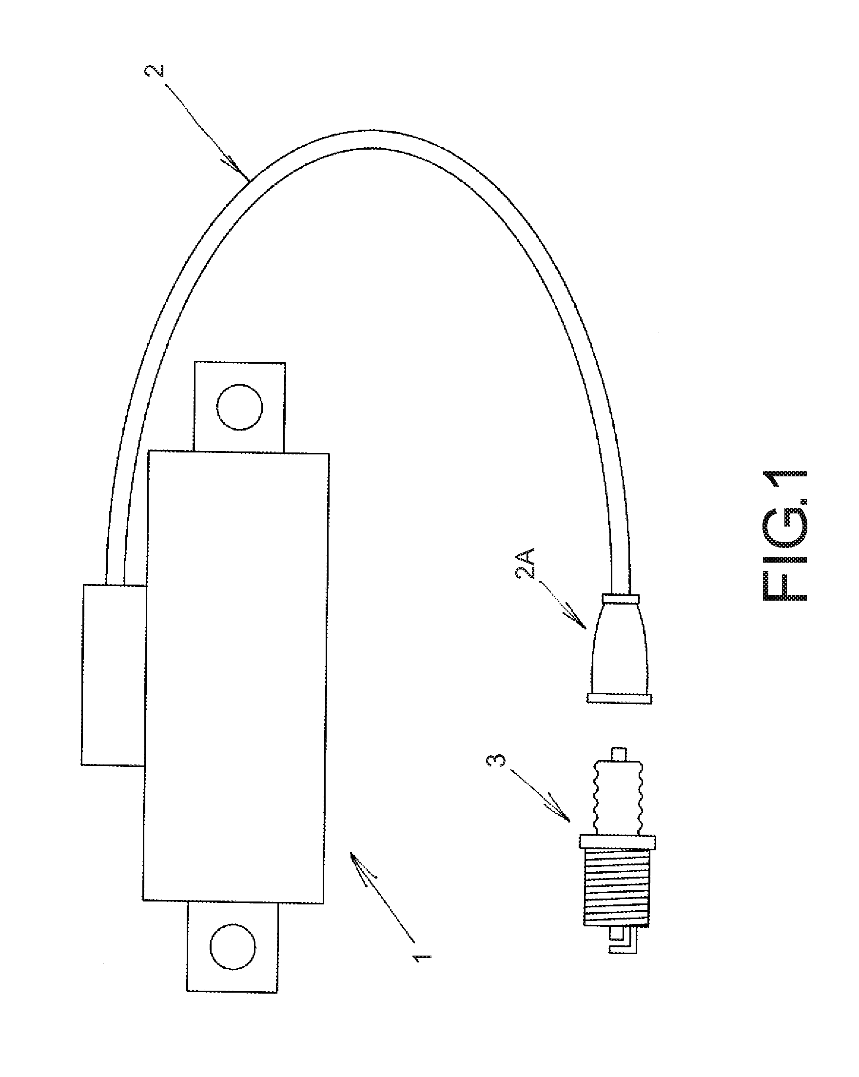
[0052]According to what is shown in the above-mentioned figures, the assembly process of a diode in a spark plug cable of an internal combustion engine, such as that provided in this invention, comprises a power supply system used in internal combustion engines, said system being schematically shown in FIG. 1, where three basic components are typically used, as follows: a) a coil unit; b) a spark plug cable; and c) a spark plug.

[0053]FIG. 1 shows a schematic view of a typical configuration, such as mentioned above, in which a coil 1, a spark plug cable 2 and its corresponding terminal (socket) 2A are shown in addition to a spark plug 3.

[0054]The purpose of said FIG. 1 is to illustrate a general view of the logic assembly sequence of said components.

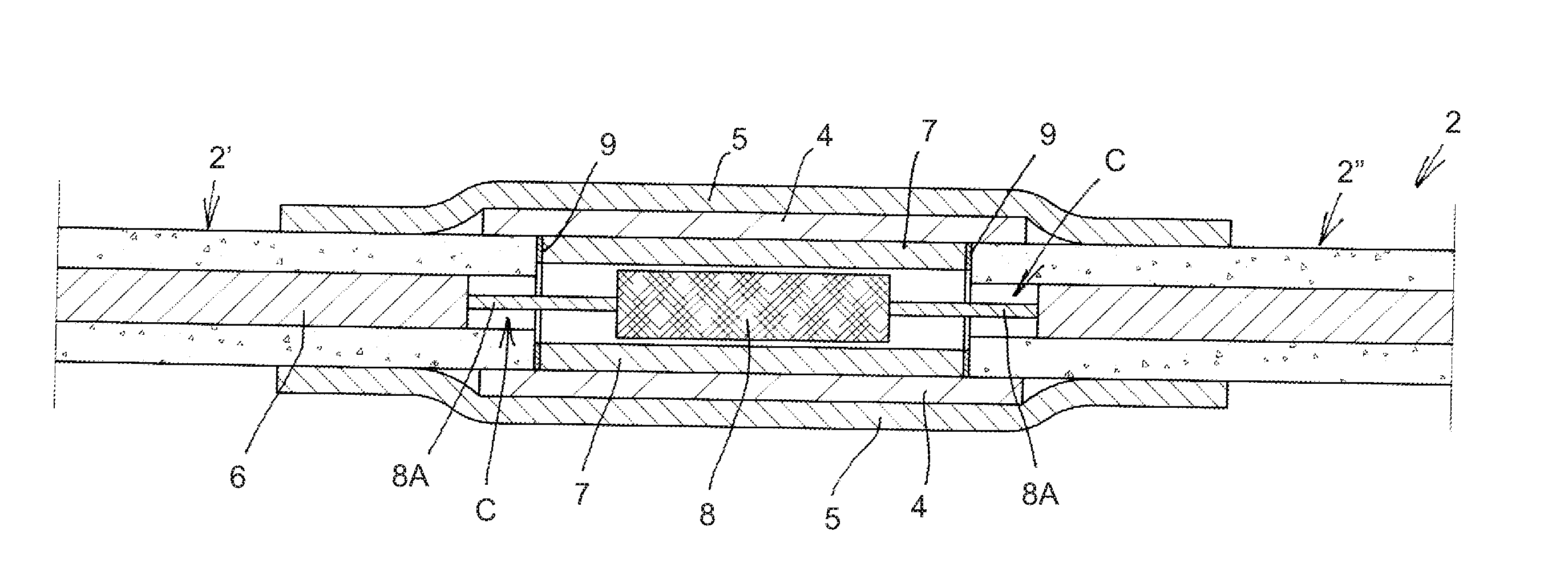
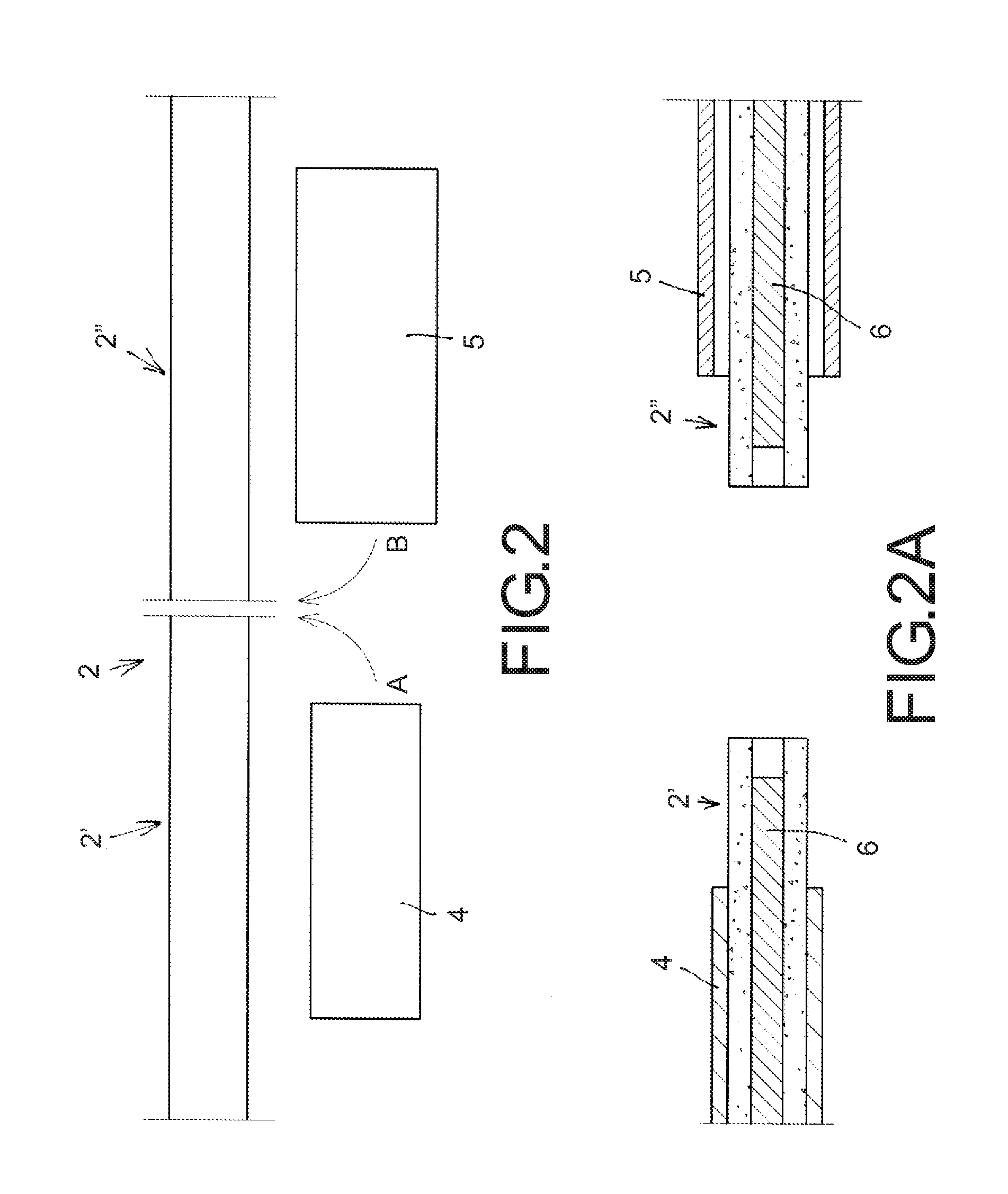
[0055]The present invention relates to a process for assembly of a diode, whose process starts by arranging the components shown in FIG. 1, and the assembly process itself may be better understood from the views provided in FIGS. 2, 2A, 2...


PUM

PropertyMeasurementUnit
Lengthaaaaaaaaaa
Currentaaaaaaaaaa
Currentaaaaaaaaaa

Abstract

Process for assembly of a diode in a spark plug cable of an internal combustion engine, suppression spark plug cable connector, manufacturing process of a suppression spark plug cable connector, spark plug connector and spark plug connection socket of internal combustion engines, said process being part of a spark plug cable (2) which is cut and receives a pipe sector (7) assembly inside which a diode (8) is located, the pipe (7) is bond between segments (2′) and (2″) of the spark plug cable (2) and receives around it a pipe-bridge (4) and a heat shrinkable cover (5); the connector (A1) featuring a diode (A2) in its inside, mounted in an encapsulated way (A2′); another connector (B1) being provided as a main cylindrical body (B2) made of injected material inside which two metal inserts (B3) are mounted in a centralized and mutual opposition arrangement, each of said inserts having a mutual contact terminal (B4) and in its respective opposite ends, a self-tapping-shaped screw terminal (B5); the socket (C1) providing mounting a diode (C10) previously encapsulated in an injected coating (C11), said diode (C10) and its coating (C12) being arranged inside a second portion (C12) of core (C5) of the socket (C1).

Description

BACKGROUND OF THE INVENTION[0001]1. Field of the Invention[0002]This description relates to a process for assembling a diode in a spark plug cable used with internal combustion engines, including those used in engines for motorcycles and related vehicles. The process herein may also be used in internal combustion engines for cars and other similar vehicles.[0003]The present invention further correlatively refers to a connector specially designed to be used together with a suppression spark plug cable for internal combustion engines, which may be both resistive cables, a modality used in most cars and similar vehicles, and non-resistive cables used in motorcycles and related vehicles, and the referred invention further relates to a manufacturing process of the spark plug cable connector disclosed herein, and said suppression spark plug cable connector having a diode.[0004]The present invention further provides a suppression / non-resistive spark plug cable connector, which is intended ...

Claims


Application Information

Patent Timeline
IPC IPC(8): H01R13/66H01R43/16H01R43/00
CPCH01R4/56H01R4/72H01R13/6641Y10T29/49204H01T13/06Y10T29/49169H01T13/04
Inventor DE ORLEANS E BRAGANCA, LUIZ PHILIPPE
Owner DE ORLEANS E BRAGANCA LUIZ PHILIPPE
Learn More