
Apparatus for replacing a cardiac valve

Inactive Publication Date: 2012-03-29
MEDTRONIC INC
View PDF5 Cites 7 Cited by
  • Summary
  • Abstract
  • Description
  • Claims
  • Application Information

AI Technical Summary

Benefits of technology

[0019]Another object of the present invention is to allow the insertion of such a valve while minimizing the risks to the patient posed by large arterial incisions.
[0020]And another object of the present invention is to simplify the precise placement of such a valve.
[0022]Another object of the present invention is to allow the insertion of a device other than a valve, such as but not limited to a valve resection tool, a decalcifying tool, an aortic valve repair tool, or a stented aortic graft, while minimizing the risks to the patient posed by large arterial incisions.
[0023]And another object of the present invention is to simplify the precise placement of a device other than a valve, such as but not limited to a valve resection tool, a decalcifying tool, an aortic valve repair tool, or a stented aortic graft.

Problems solved by technology

Unfortunately, this procedure is a substantial and invasive undertaking for the patient.
While there have been significant advances in heart valve technology over the past 30 years, there has been little progress in the development of safer and less invasive valve delivery systems.
Given the current invasiveness of this procedure and the requirement to utilize cardiopulmonary bypass, aortic valve replacement surgery is associated with a high risk of morbidity and mortality.
Using the technology available at that time, success was limited: the valve area was increased only minimally, and nearly all patients had restenosis within one year.
However, these approaches still require cardiopulmonary bypass and cardiac arrest, which themselves entail significant morbidity and a prolonged post-operative recovery.
Unfortunately, although there has been great progress in the treatment of coronary artery disease without cardiopulmonary bypass (e.g., angioplasty, with or without stenting, and “off-pump” coronary artery bypass grafting), similar advances have not yet been realized in heart valve surgery.
The first challenge is to remove the diseased valve without causing stroke or other ischemic events that might result from the liberation of particulate material while removing the diseased valve.
The second challenge is to prevent cardiac failure during removal of the diseased valve.
However, as the diseased valve is removed, it becomes acutely and severely incompetent, causing the patient to develop heart failure which results in death unless the function of the valve is taken over by another means.
Therefore, any sizable incision made to the aorta in order to insert a standard valve prosthesis into the arterial system creates the potential for uncontrollable bleeding from the incision site.
Furthermore, even if bleeding is successfully controlled, pressures within the aorta may result in weakening of the aorta caused by aortic wall dissection.
In addition, large incisions on the aorta also increase the potential for liberating plaque from the aortic wall that can lead to embolic complications.
Unfortunately, however, none of these relatively flimsy valve prostheses have proven adequate to endure the repetitive stresses undergone by the aortic valve over the ten to twenty years typically required.
In addition to the foregoing, the precise placement of such expandable prosthetic valves in the correct sub-coronary position can be extremely challenging, particularly in view of the high pressure, pulsatile blood flow passing through the aorta.
Furthermore, expandable prosthetic valves would typically be positioned from a remote artery, which would reduce the ability to precisely control the placement and positioning of the device and therefore would increases the risk of obstructing the coronary arteries.

Method used


Image

  • Apparatus for replacing a cardiac valve
  • Apparatus for replacing a cardiac valve
  • Apparatus for replacing a cardiac valve

Examples


Embodiment Construction

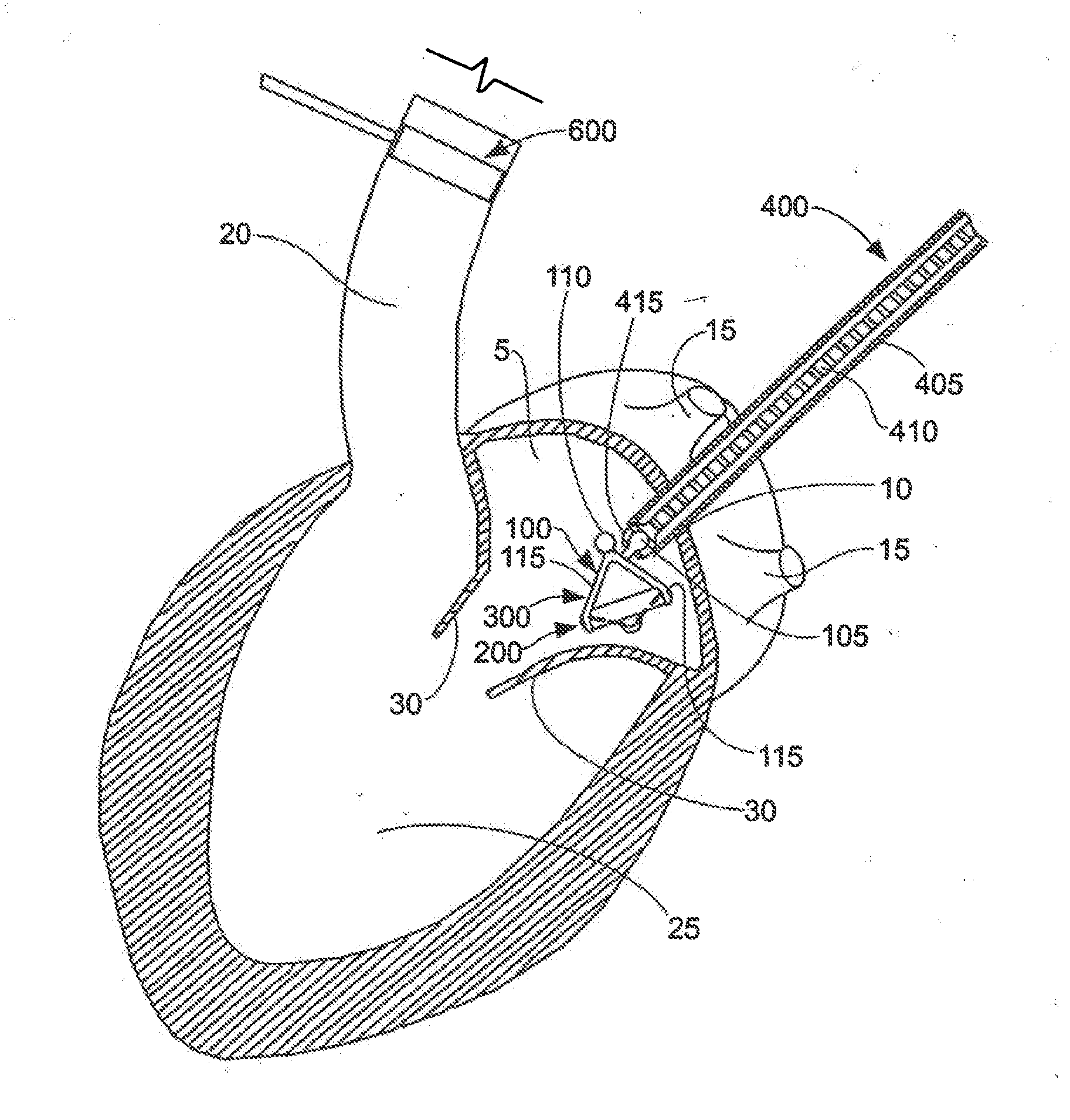
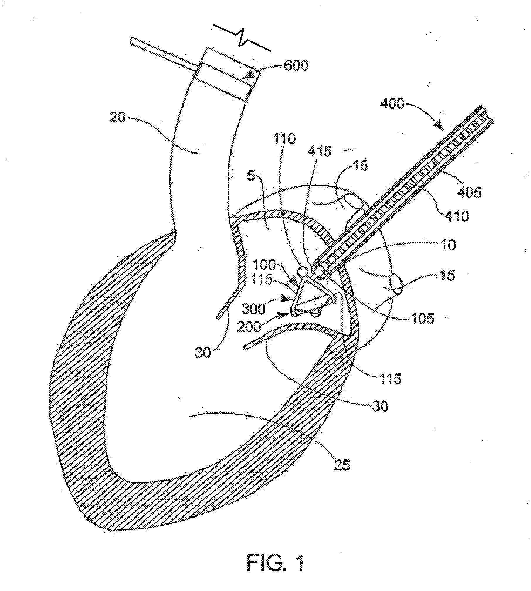
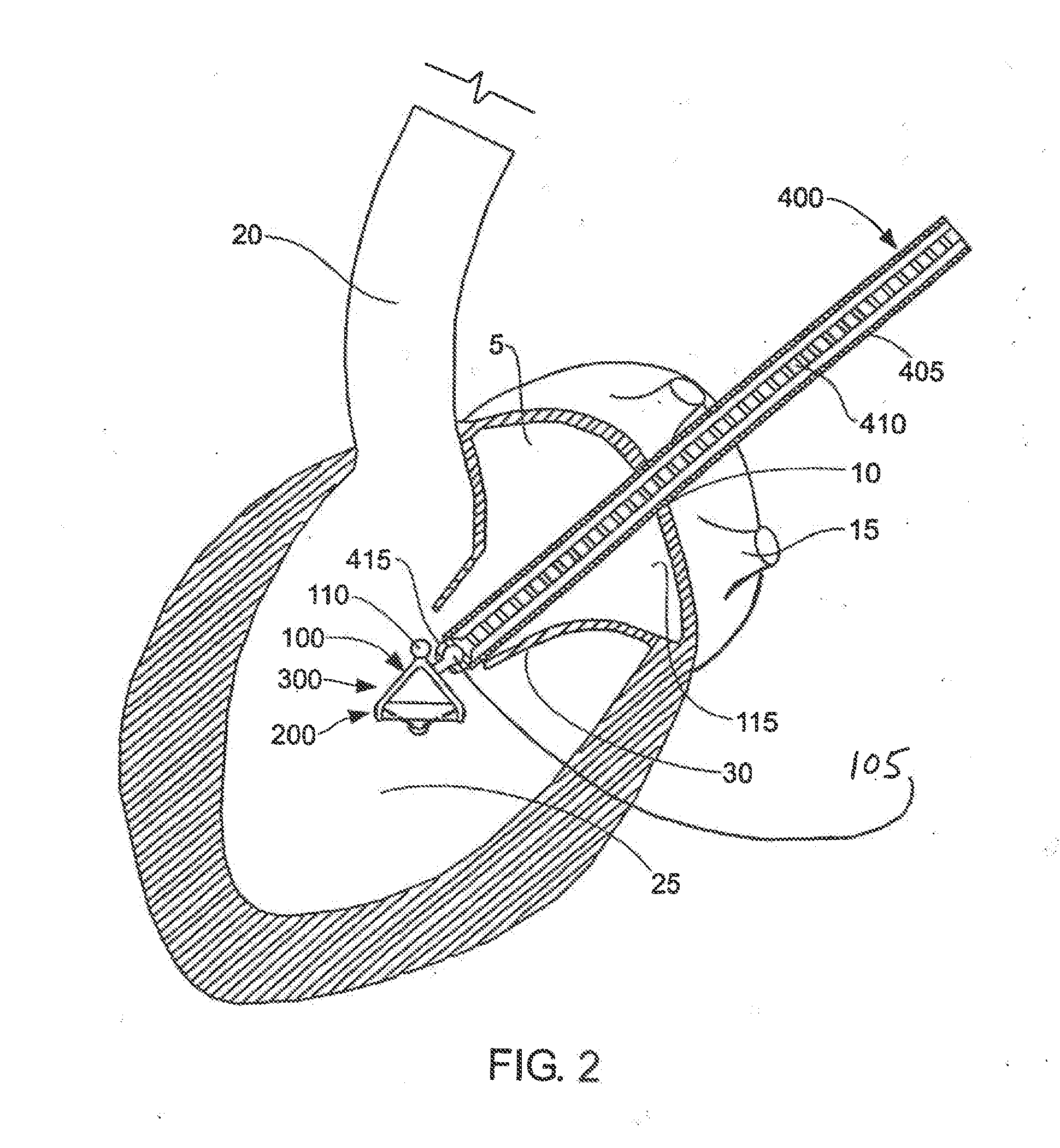
[0069]The present invention can be used to deliver or implant a variety of prostheses into the arterial system or left side of the heart. The prosthesis used in the preferred embodiment is an aortic valve prosthesis. Alternatively, the prosthesis may comprise, but is not limited to, a cylindrical arterial stent, an arterial prosthesis or graft, a ventricular assist device, a device for the treatment of heart failure such as an intraventricular counterpulsation balloon, chordae tendinae prostheses, arterial filters suitable for acute or chronic filtration of emboli from the blood stream, arterial occlusion devices and the like.

[0070]For clarity of illustration, the present invention will hereinafter be discussed in the context of implanting an aortic valve prosthesis.

[0071]It should also be appreciated that the present invention may be practiced either “on-pump” or “off-pump”. In other words, the present invention may be performed either with or without the support of cardiopulmonary...


PUM


Abstract

A prosthetic heart valve in combination with a delivery assembly that includes a first elongate component that is movably disposed to a second elongate component. The delivery assembly has a temporary valve location relative to the delivery assembly to which the prosthetic heart valve can be releasably mounted in position and a spaced implantation location relative to the delivery assembly to which the prosthetic heart valve can also be releasably mounted in position. The prosthetic heart valve and delivery assembly combination is configurable with movement of the first elongate component relative to the second elongate component from a delivery state with the prosthetic heart valve mounted in the temporary location to an implantation state with the prosthetic heart valve repositioned from the temporary, location to the implantation location so that the prosthetic heart valve can subsequently be deployed from the implantation location.

Description

CROSS-REFERENCE TO RELATED APPLICATION[0001]The present application is a continuation application of U.S. patent application Ser. No. 10 / 894,677, filed Jul. 19, 2004, now allowed, which is a continuation-in-part of U.S. Pat. No. 7,201,761, issued Apr. 10, 2007, which is a continuation-in-part of U.S. Pat. No. 6,769,434, issued Aug. 3, 2004, which claims priority to U.S. Provisional Application No. 60 / 488,548, filed Jul. 18, 2003, and titled “Method and Apparatus for Resecting and Replacing an Aortic Valve”, the entire contents of which are incorporated herein by reference in their entirety.FIELD OF THE INVENTION[0002]This invention relates to apparatus and methods for performing cardiac surgery in general, and more particularly to apparatus and methods for performing cardiac surgery while the heart is beating.BACKGROUND OF THE INVENTION[0003]Of all valvular heart lesions, aortic stenosis carries the worst prognosis. Within one year of diagnosis, approximately half of all patients wi...

Claims


Application Information

Patent Timeline
IPC IPC(8): A61F2/24A61B17/32
CPCA61F2/2427
Inventor COHN, WILLIAM E.
Owner MEDTRONIC INC
Features
  • Generate Ideas
  • Intellectual Property
  • Life Sciences
  • Materials
  • Tech Scout
  • Unparalleled Data Quality
  • Higher Quality Content
  • 60% Fewer Hallucinations
Learn More