
Ultra wide band antenna

a wideband antenna and ultrawideband technology, applied in individual energised antenna arrays, resonant antennas, coatings, etc., can solve the problems of narrow bandwidths of standard dipole and monopole antennas, too large applications in user equipment, and inability to cover the operating bands of 4 g communications, so as to improve the vswr and reduce the size of ultrawideband antennas , the effect of increasing the bandwidth

Inactive Publication Date: 2012-04-05
TE CONNECTIVITY GERMANY GMBH
View PDF11 Cites 15 Cited by
  • Summary
  • Abstract
  • Description
  • Claims
  • Application Information

AI Technical Summary

Benefits of technology

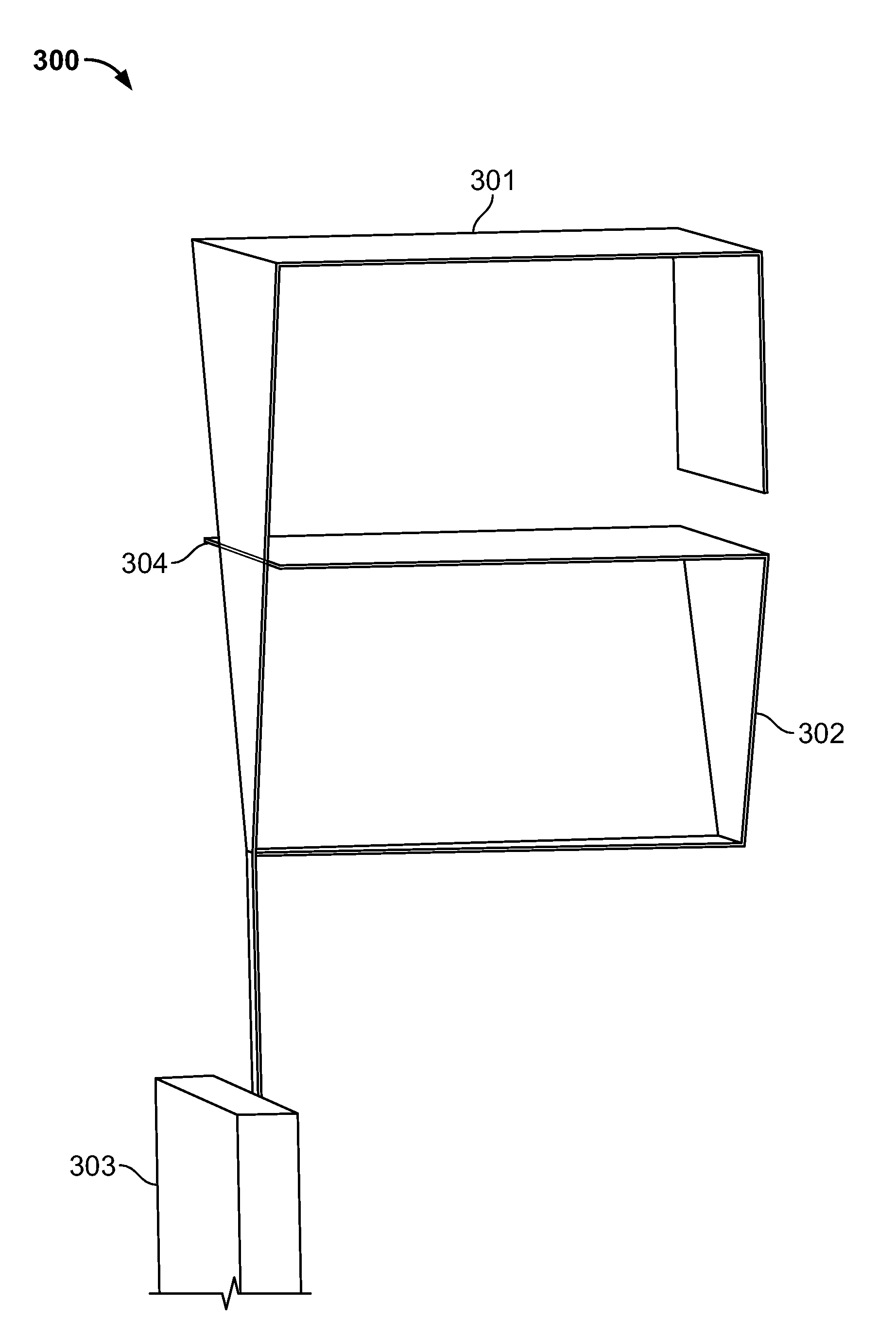
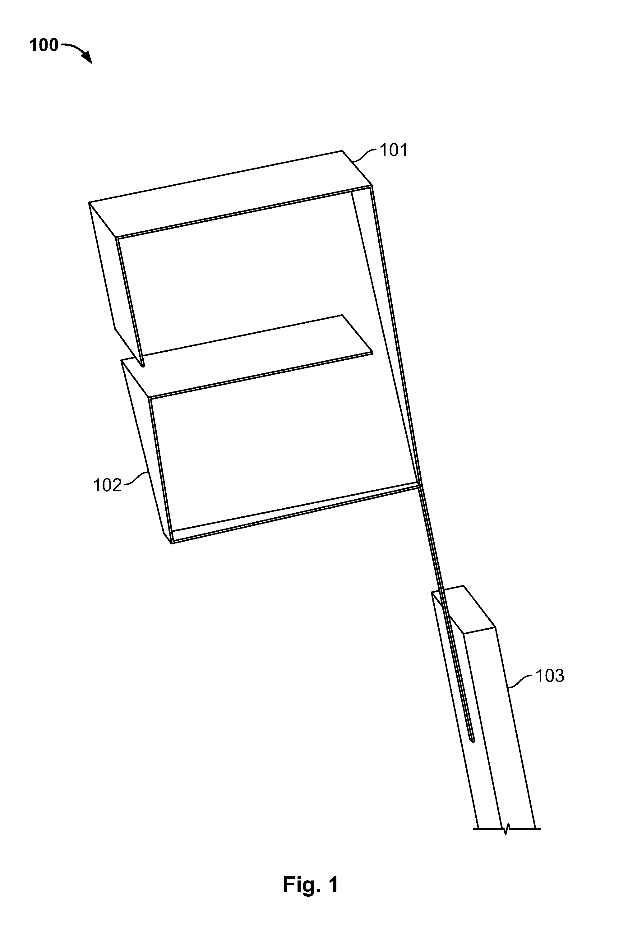
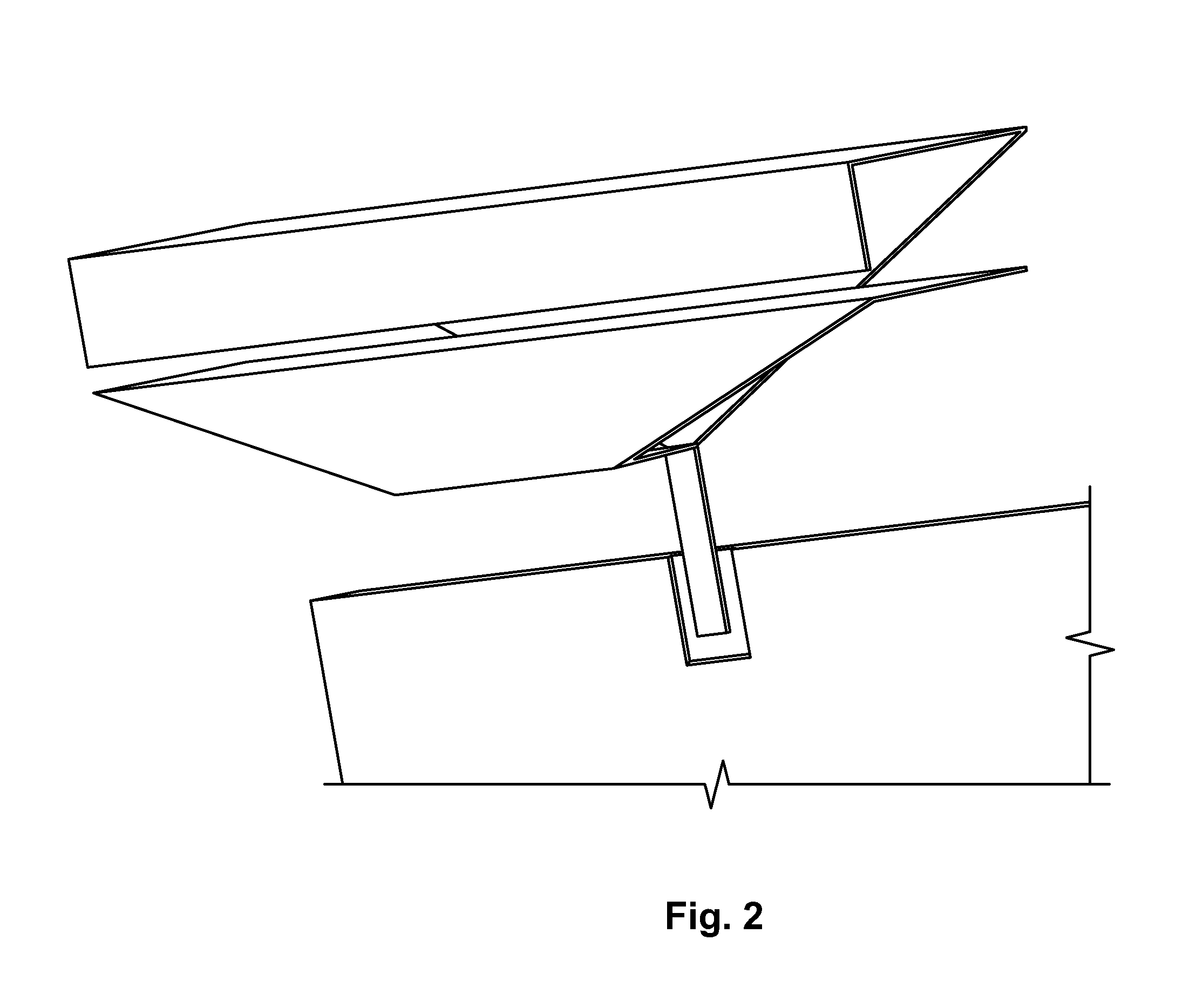
[0021]Having an ultrawideband antenna for use in a communications equipment that comprises a first folded branch antenna element with an electrical connection at a first end and a second folded branch antenna element with an electrical connection at a first end has the advantage of having a small size antenna of ultrawide bandwidth.
[0033]Having a third folded branch antenna element with an electrical connection at a first end in the ultrawideband antenna has the advantage of being able to improve the VSWR further, or increasing the bandwidth.

Problems solved by technology

One of the research challenges in LTE is the broad frequency range i.e. 698 MHz to 2690 MHz, of the interface between the user equipment (UE) and the eNODE B. If standard half-dipoles or quarter wavelength monopole antennas were to be used, the size of the antenna would be about 21 cm or 10.5 cm for the low frequency range.
This would appear too large for the application in the user equipment, mobile phones for example.
Moreover, the bandwidths of standard dipole and monopole antennas are too narrow to cover the operating bands of 4 G communications.
Unfortunately, branch antennas may transmit and receive electrical signals within a band of frequencies that is too narrow to satisfy the needs of LTE and 4G or that hardly has the margin to take into account the surrounds of a UE.
Unfortunately, as the meandering pattern of a radiating element becomes more compressed, the frequency band within which the radiating element can operate typically becomes narrower.

Method used


Image

  • Ultra wide band antenna
  • Ultra wide band antenna
  • Ultra wide band antenna

Examples


Embodiment Construction

[0044]Herein a more detailed description based on embodiments of the present invention with reference to the accompanying drawings is provided.

[0045]First, a preferred embodiment will be described. However, the present invention should not be construed as limited to the embodiments set forth herein. Rather these embodiments are provided so that this disclosure will be thorough and complete and will fully convey the scope of the invention to those skilled in the art. In the drawings like numbers refer to like elements throughout.

[0046]In particular, the antenna of this preferred embodiment is described in the context of being used in a mobile communication equipment in an LTE or 4G network. It is, however, conceivable that small ultra wideband antennas could be used in many different circumstances, including fixed wireless access, WLAN, WiFi, etc.

[0047]Throughout the following description, the two-branch antenna is described as being used in a mobile communications equipment which co...


PUM


Abstract

An ultrawideband antenna for use in communications equipment, comprising a first folded branch antenna element with an electrical connection at a first end and a second folded branch antenna element with an electrical connection at a first end. The folded branch antenna elements are of a triangular shape, or a combination of polygonal shapes. By using the present invention, the volume of an antenna is reduced and the ultra wide bandwidth can be achieved.

Description

BACKGROUND OF THE INVENTION[0001]1. Field of the Invention[0002]The present invention relates to an ultrawideband antenna device of small dimensions to be used in the communications equipment.[0003]2. Related Art to the Invention[0004]With the success of second generation and third generation wireless communication the fourth generation (4G) or long term evolution (LTE) is now being developed. 4G / LTE mobile communications provide wideband multimedia services at high data rates.[0005]The LTE specification provides downlink peak rates of at least 100 Mbps and an uplink of at least 50 Mbps and RAN round-trip times of less than 10 ms. LTE supports scalable carrier bandwidths from 1.4 MHz to 20 MHz and supports both frequency division duplexing (FDD) and time division duplexing (TDD). The next step for LTE evolution is LTE advanced and is currently being standardized in 3GPP release 10. The standard includes that five different terminal classes have been defined from a voice centric clas...

Claims


Application Information

Patent Timeline
IPC IPC(8): H01Q1/38B05D1/36B05D5/12H01Q5/10
CPCH01Q1/36H01Q21/30H01Q9/42H01Q5/00H01Q9/16H01Q9/44H01Q21/08H01Q9/0414H01Q5/371
Inventor PAN, SHENG-GEN
Owner TE CONNECTIVITY GERMANY GMBH
Learn More