Regulating the Temperature of a Heat Regenerator Used in an Installation for Storing Energy by Adiabatic Compression of Air

a technology of adiabatic compression and heat regeneration, which is applied in the direction of regenerative heat exchangers, engine fuctions, lighting and heating apparatus, etc., can solve the problems of low electrical efficiency (less than 50%), poor satisfaction of diabatic installations, and low electrical efficiency

Inactive Publication Date: 2012-04-12
GDF SUEZ SA
View PDF6 Cites 23 Cited by
  • Summary
  • Abstract
  • Description
  • Claims
  • Application Information

AI Technical Summary

Benefits of technology

[0008]A main object of the present invention is thus to mitigate such drawbacks by proposing a method of regulating the heat regenerator that enables it to perform the two above-mentioned thermal functions effectively over a large number of operating cycles.

Problems solved by technology

Some such installations are said to be “diabatic” since they do not recover the heat that results from compressing air during the compression stages.
As a result, they present relatively low electrical efficiency (less than 50%).
They are also polluting since they eject CO2 emissions that result from burning a fossil fuel, as is essential for preheating the air before it is sucked into the air turbines during the expansion stages.
Such diabatic installations are therefore poor at satisfying the new European Community requirements concerning energy, economic, and environmental performance that require energy installations to be implemented that present high efficiency and that are environmentally friendly.
Unfortunately, if the regenerator is not regulated efficiently, then the temperature of the air at the outlet from the regenerator during compression will increase progressively over successive operating cycles of the installation because the amount of energy extracted from the regenerator during the expansion stages does not compensate the quantity of heat stored during compression stages, in spite of heat losses through the walls.
This temperature hysteresis is unacceptable since air temperatures above a critical threshold (about 50° C.) at the inlet to the storage capacity cannot be tolerated.
Exceeding this threshold requires the operation of the installation to be stopped immediately on pain of rapidly degrading the organic layer in the storage capacity (by heating it excessively), or even of causing the steel involved in its design to buckle (by losing mechanical strength as a result of going beyond the limit for plastic deformation).
Furthermore, progressive and irreversible overheating of the regenerator makes it impossible to perform any kind of control of its outlet temperatures.

Method used


Image

  • Regulating the Temperature of a Heat Regenerator Used in an Installation for Storing Energy by Adiabatic Compression of Air
  • Regulating the Temperature of a Heat Regenerator Used in an Installation for Storing Energy by Adiabatic Compression of Air
  • Regulating the Temperature of a Heat Regenerator Used in an Installation for Storing Energy by Adiabatic Compression of Air

Examples


Embodiment Construction

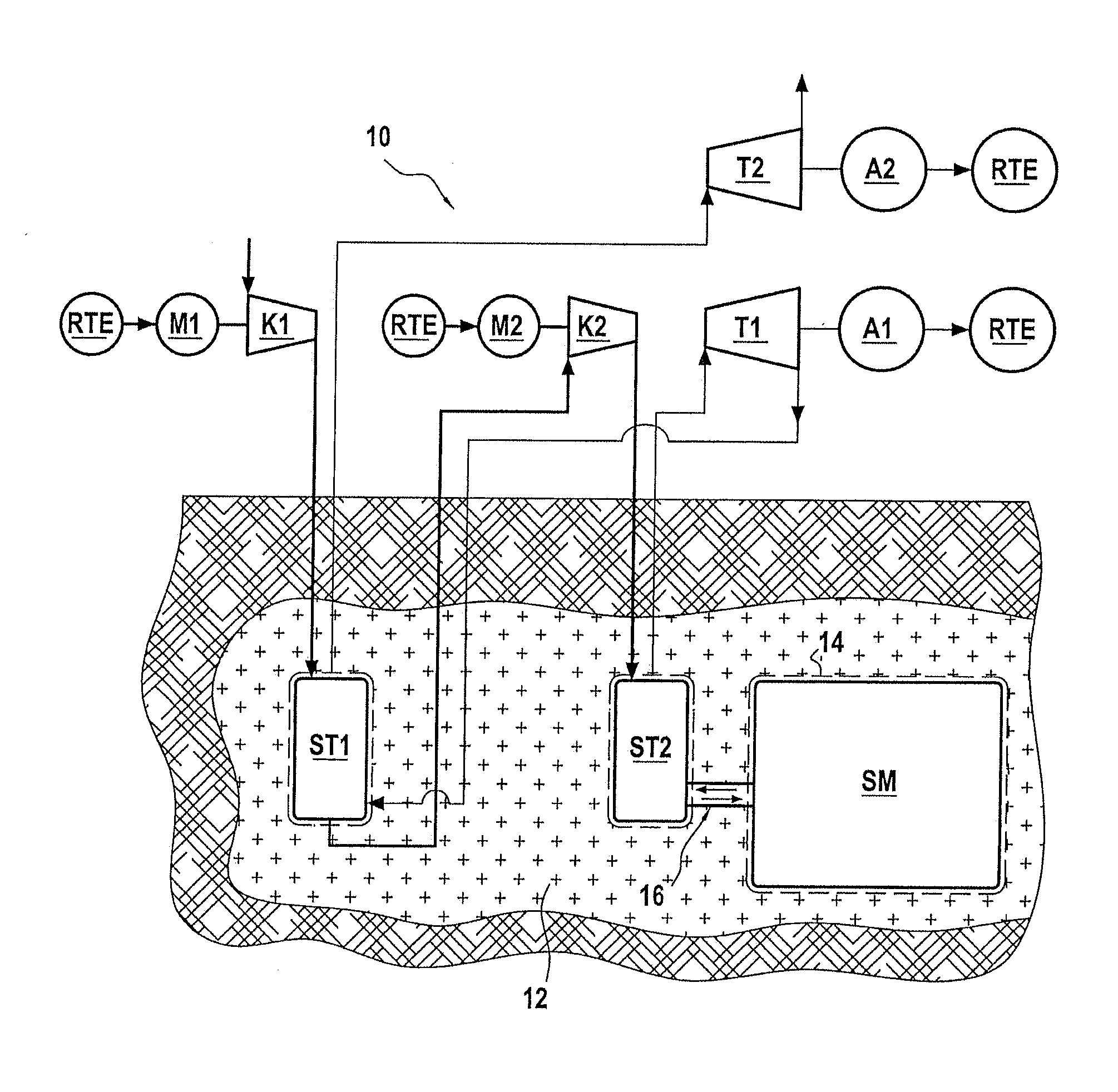
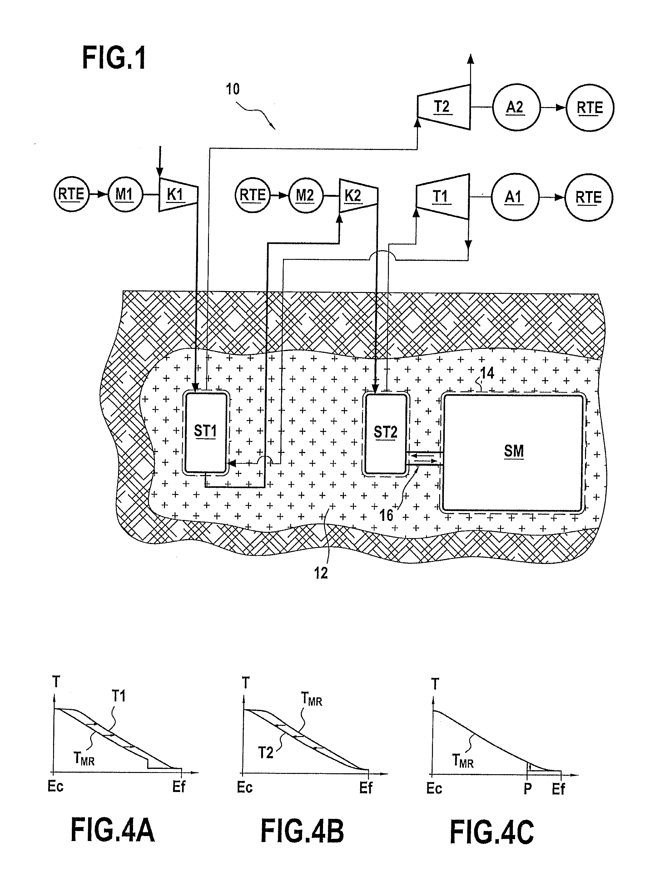
[0024]FIG. 1 is a highly diagrammatic view of an installation 10 for mass storage of energy (i.e. several gigawatts (GW) thermal) by adiabatic compression of air in accordance with the invention.

[0025]The invention 10 comprises one or more compression stages (there being two in FIG. 1, corresponding to a medium compression stage and a high compression stage) together with one or more expansion stages (there likewise being two in FIG. 1).

[0026]Each compression stage comprises an axial or a radial type compressor (i.e. a medium-pressure compressor K1 and a high-pressure compressor K2) driven by a respective electric motor M1 or M2, the motor being electrically powered from the electricity transmission network RTE. Similarly, each expansion stage comprises an air turbine T1, T2 connected to an alternator A1, A2 in order to deliver electricity to the electricity transport network RTE.

[0027]The installation 10 also has a lined excavated cavity SM in which the air compressed by the compre...


PUM


Abstract

The invention relates to a method of regulating the temperature of a heat regenerator (ST1, ST2) used in an installation (10) for storing energy by adiabatic compression of air. The regenerator is subjected to successive operating cycles, each cycle comprising a compression stage followed by an expansion stage. Between two successive cycles, the method consists in cooling a bottom compartment (26a) of the layer of refractory material (26) of the regenerator that is situated in the proximity of the bottom distribution box (24) in order to bring the air leaving the heat regenerator to a temperature that is compatible with the range of temperatures required during the compression stages. The invention also provides such a heat regenerator.

Description

BACKGROUND OF THE INVENTION[0001]The present invention relates to the general field of mass storage of energy by compressing air. It relates more particularly to controlling the temperature of a heat regenerator used in an installation for storing energy by adiabatic compression of air.[0002]Storing energy by compressing air consists in storing compressed air for subsequent use as a source of mechanical energy. Typically, the installations that are used for this type of energy storage are subjected to successive operating cycles, each operating cycle comprising a compression stage during which the air is compressed to high pressure and stored in a storage cavity, and an expansion stage during which electricity is produced by expanding the compressed air through air turbines driving alternators.[0003]The principle of storing energy by compressing air is to take advantage of price differences for electricity between so-called “off-peak” hours during which electricity rates are less ex...

Claims


Application Information

Patent Timeline
Patent Type & Authority Applications(United States)
IPC IPC(8): F15B1/027F28F7/00F28D15/00
CPCF02C6/16F05D2260/211Y02E60/15F28D17/02Y02E60/16
Inventor CANAL, PATRICKNADAU, LIONEL
Owner GDF SUEZ SA
Why Eureka
Try Eureka