
Wireless communication system, integrated base station, and terminal

Inactive Publication Date: 2012-04-12
HITACHI LTD
View PDF4 Cites 48 Cited by
  • Summary
  • Abstract
  • Description
  • Claims
  • Application Information

AI Technical Summary

Benefits of technology

[0014]In the one-to-N BC: Broadcast Channel in Non-Patent Document 2, as compared with the one-to-one eigenmode propagation method disclosed in Non-Patent Document 4, the total number of antennas on the receiving side is increased as increasing the number of users, and therefore, the communication capacity which can be provided in the entire system is increased.
[0017]Also, Non-Patent Document 5 does not disclose a clear communication procedure indicating either that the coordinated communication among the plurality of base stations is always operated or that the communication between one base station and its tributary terminal is conventionally carried out. In the above-described inter-base-station coordinated communication method, which carries out the simultaneous communication with the plurality of terminals by the cooperation of the plurality of base stations, there is a possibility of increasing the capacity which can be provided by the system. On the other hand, by the increase in the number of terminals or the number of transmitting / receiving antennas simultaneously handled by the system, an amount of the channel information communicated between the transmission / reception sides is increased, the overhead for feeding back the channel information measured at the terminals is increased, and therefore, the practical increase in the throughput is not obtained in some cases. The terminals have various pieces of information such as a stopping channel and a moving channel. Therefore, in order to always newly maintain the channel information which is momentarily varied, it is required to carry out this feedback at an appropriate timing.
[0019]With assuming a wireless system using a plurality of transmitting / receiving antennas, a preferred aim is to provide a communication method of selecting an optimal communication mode as satisfying communication speed requested by terminals. Also, for the problem of the increase in the feedback amount when the communication method is switched, a preferred aim is to provide a method of decreasing the feedback amount so as to provide a communication method of preventing decrease in the frequency utilization efficiency.
[0023]From the acknowledgment of the information of feedback judgment, the terminal autonomously determines whether the feedback information is to be transmitted or not, so that the feedback amount provided when the number of terminals is increased can be decreased. On the base station side, by resetting a threshold value of the information of the feedback judgement, the feedback information can be obtained more from the terminals, or, conversely, can be reduced. In consideration of a tradeoff relationship between the situation of the desired feedback precision and the amount of the feedback information, the feedback amount can be controlled on the base station side.
[0024]Also, instead of relying on the base station side alone for all of the processes to determine any of the communication methods of the inter-base-station time division multiplex communication, the interference avoiding inter-base-station simultaneous communication, and the inter-base-station coordinated communication, the estimated communication speed in each communication method is obtained on the terminal side, and the judgment whether the speed satisfies the requested communication speed or not is carried out by the distributed processing, so that the calculation time for determining the communication method on the base station side can be significantly reduced. In this manner, the communication methods can be switched at a short control cycle, and therefore, the followability for the channel variation can be improved, and the performance deterioration can be prevented.

Problems solved by technology

Therefore, when the variation of the wireless propagation path is large, there is a demerit that the communication performance is deteriorated since the actual channel state upon the communication is different from the fed-back channel state.
The channel is varied during delay time taken for this feedback, and therefore, the performance is largely deteriorated, and it is difficult to achieve means of the disclosures.
Further, in the communication capacity of the one-to-N Broadcast Channel, the communication capacity which can be provided is limited by restrictions on the number of antennas of the transmitting station.

Method used


Image

  • Wireless communication system, integrated base station, and terminal
  • Wireless communication system, integrated base station, and terminal
  • Wireless communication system, integrated base station, and terminal

Examples


Embodiment Construction

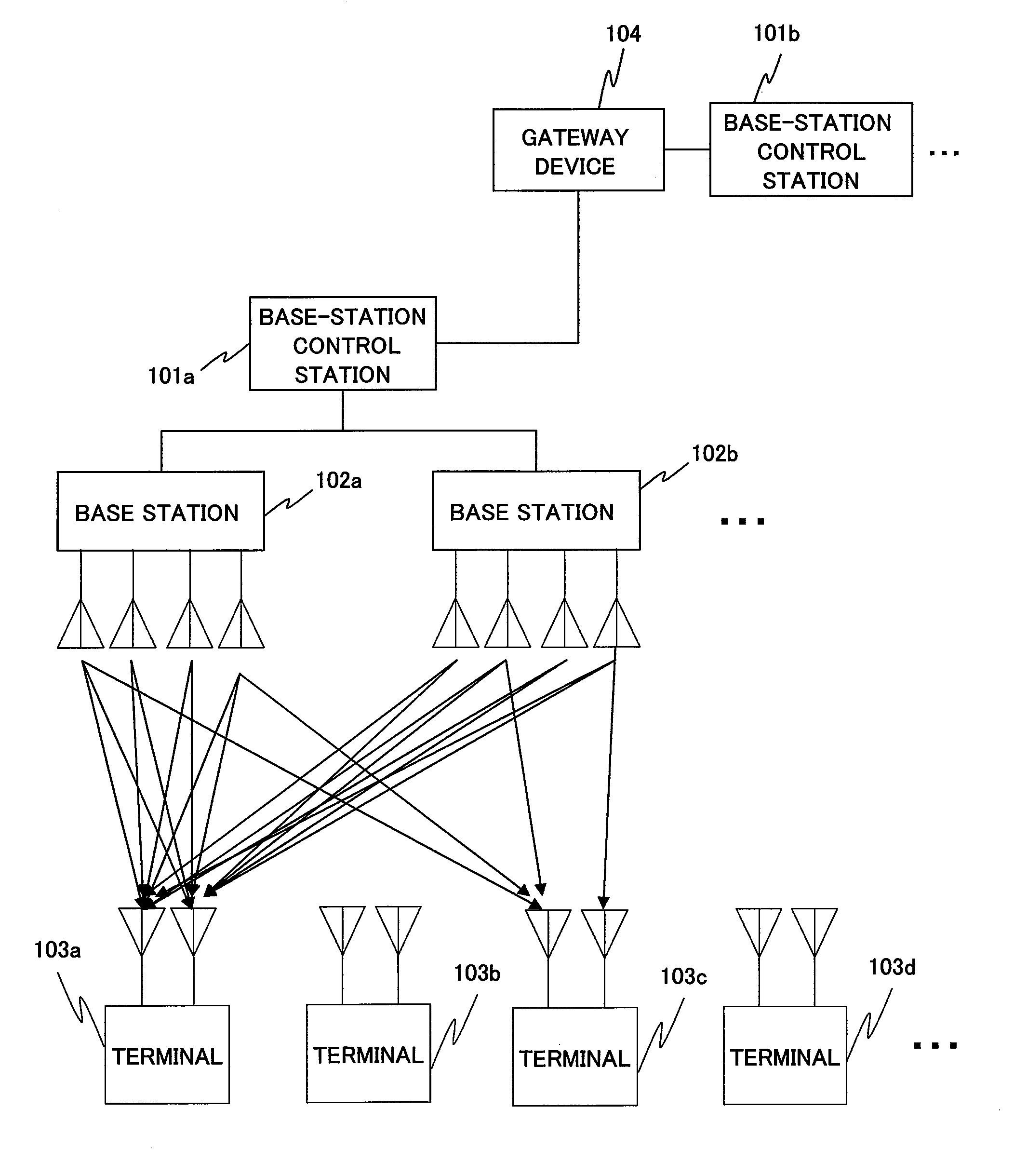
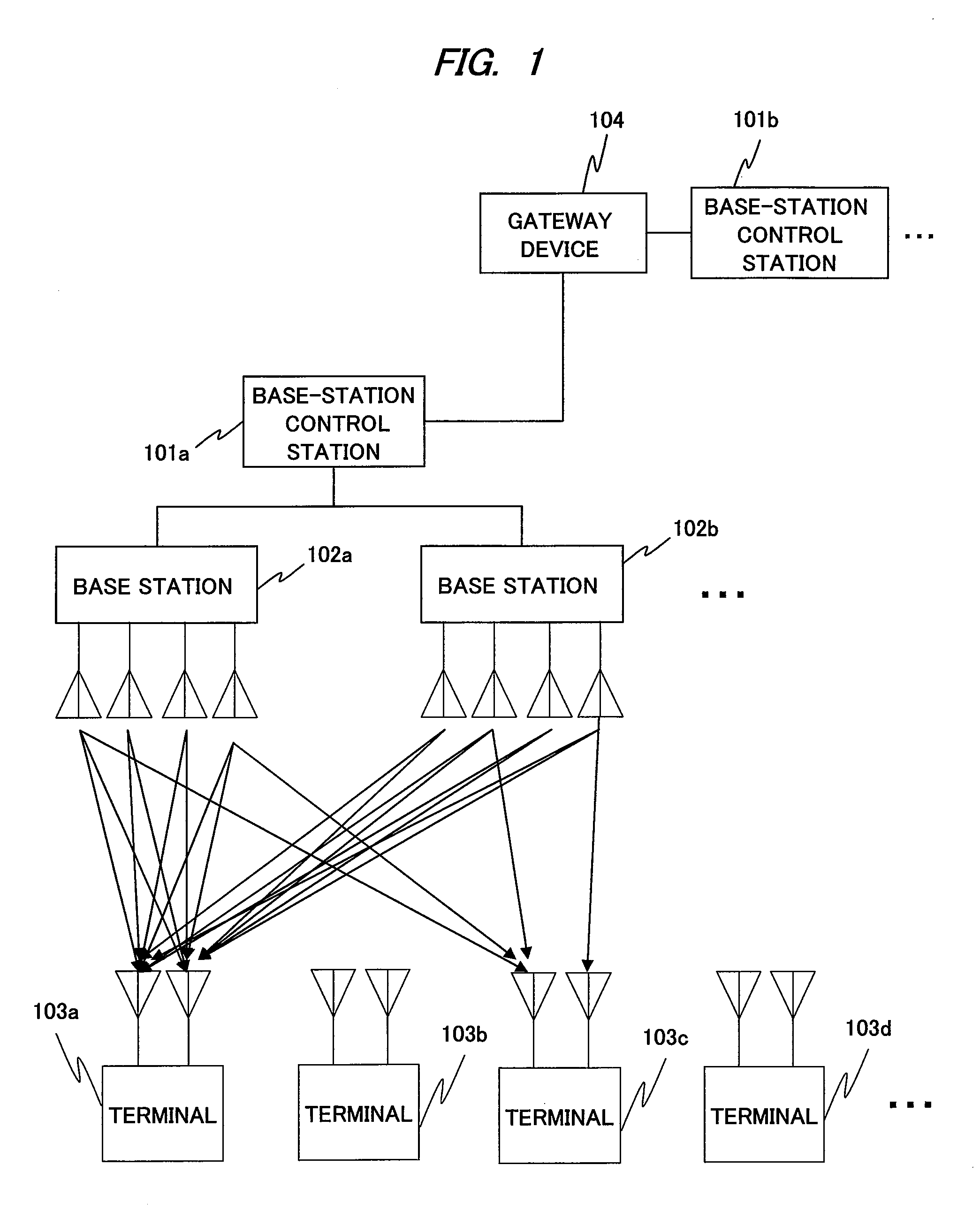
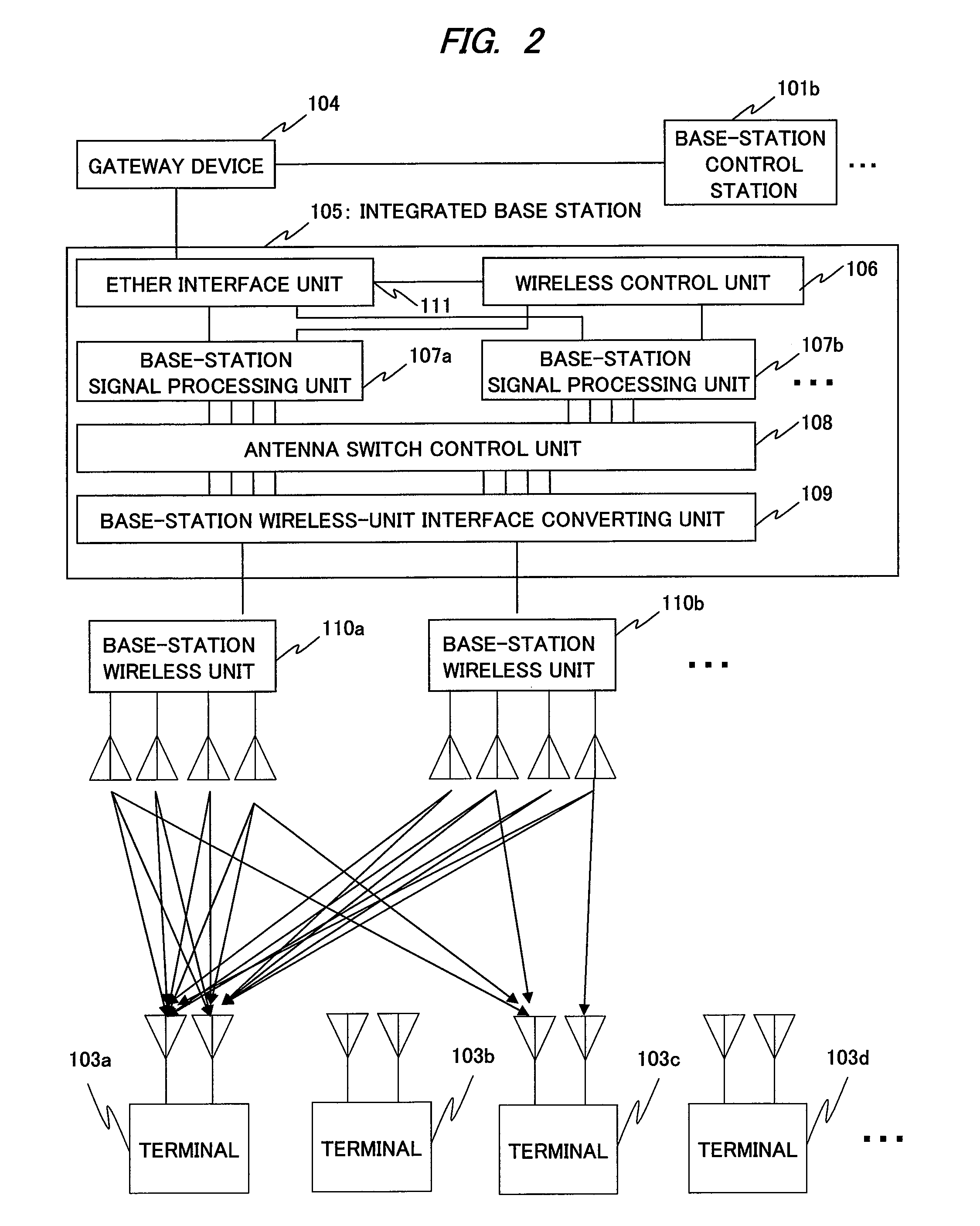
[0046]With respect to FIG. 1, a wireless system entire configuration is explained. A base-station control station 101a controls belonging base stations 102a, 102b, and . . . to achieve the coordinated cooperating communication among the base stations. An example of FIG. 1 shows a state that the base station 102a and the base station 102b carry out the inter-base-station coordinated communication to transmit a data to terminals 103a and 103c at a certain point of time. The terminals 103a and 103c separate a desired signal to carry out a receiving processing. At this time, the base-station control station forms a transmitting signal for inter-base-station coordinated transmission, and acquires the channel information for total four receiving antennas of the terminals 103a and 103c with using total eight transmitting antennas of the base station 102a and the base station 102b, so that the signal processing for 8×4 Broadcast Channel is carried out.

[0047]Also, the base-station control st...


PUM


Abstract

A frame time having a certain period of time is divided into: a time period (for inter-base-station time division multiplex communication) in which one of the base stations has a transmission right in the simultaneous transmission and carries out inter-base-station time division multiplex communication so as to avoid interference between the base stations; and a time period (for inter-base-station simultaneous communication) for communication which is simultaneously carried out between the plurality of base stations. Furthermore, the time periods are switched for the communication.

Description

TECHNICAL FIELD[0001]The present invention relates to a method of carrying out data transmission / reception between a plurality of base stations having a plurality of transmitting / receiving antennas and a plurality of tributary terminals of the respective base stations in a wireless communication system.BACKGROUND ART[0002]In recent years, along with increasing speed of a wireless communication system, a MIMO (Multiple Input Multiple Output) technique of transmitting data from a plurality of antennas and receiving data by a plurality of antennas has been employed to many wireless standards of wireless LAN, mobile communication, and others, from a viewpoint of improving a frequency utilization efficiency.[0003]In one-to-one wireless communication (Point to Point) between one transmitting station and one receiving station, an eigenmode propagation method which is disclosed in Non-Patent Document 4 is known as a method of maximally bringing out a communication capacity provided by a wir...

Claims


Application Information

Patent Timeline
IPC IPC(8): H04W24/00H04J3/00H04L12/26
CPCH01Q1/246H04B7/024H04B7/0452H04B7/0626H04B7/0639H04B7/0645H04B7/0465H04W24/10H04W28/04H04W48/18H04W88/06H04W88/08H04W92/20H04W24/00
Inventor TAMAKI, TSUYOSHIYANO, TAKASHIJIA, YUNJIAN
Owner HITACHI LTD
Learn More