Structure for railroad ties having data acquisition, processing and transmission means

Inactive Publication Date: 2012-04-19
TJ TECH HLDG
View PDF11 Cites 16 Cited by
  • Summary
  • Abstract
  • Description
  • Claims
  • Application Information

AI Technical Summary

Benefits of technology

[0011]In light of the foregoing, it is a first aspect of the invention to provide a composite structure for railroad ties and the like that are configured to securely retain

Problems solved by technology

Treated solid wood ties, however, have a relatively short useful life span of five to fifteen years before they have deteriorated to the point that they must be replaced, and they often require significant maintenance during that life span.
The use of spikes driven into the wood ties to secure the steel rails contributes significantly to the short life of such ties.
The oscillating loads imparted to the rail spikes securing the rail gage result in split ties and ejected spikes, both contributing to the need for early replacement or maintenance.
From an environmental perspective the use of solid wood ties is undesirable for several reasons, including the depletion of timber resources that could be put to better uses, and the use of toxic chemicals in the preservative treatment of the ties.
Concrete ties have a longer life span than wooden ties, but they are substantially more costly than wood.
Concrete ties also require different installation techniques, since conventional spikes cannot be driven into concrete.
The ties, and the methods of producing them known in the prior art, are not without disadvantages and drawbacks, however.
The most significant problems with the plastic ties themselves include the flex behavior of the crosstie beam and they do not securely retain spikes used to attach rails to the ties nearly as effectively as wooden ties.
The flex behavior adversely affects rail performance and displaces ballas

Method used


Image

  • Structure for railroad ties having data acquisition, processing and transmission means
  • Structure for railroad ties having data acquisition, processing and transmission means
  • Structure for railroad ties having data acquisition, processing and transmission means

Examples


Example

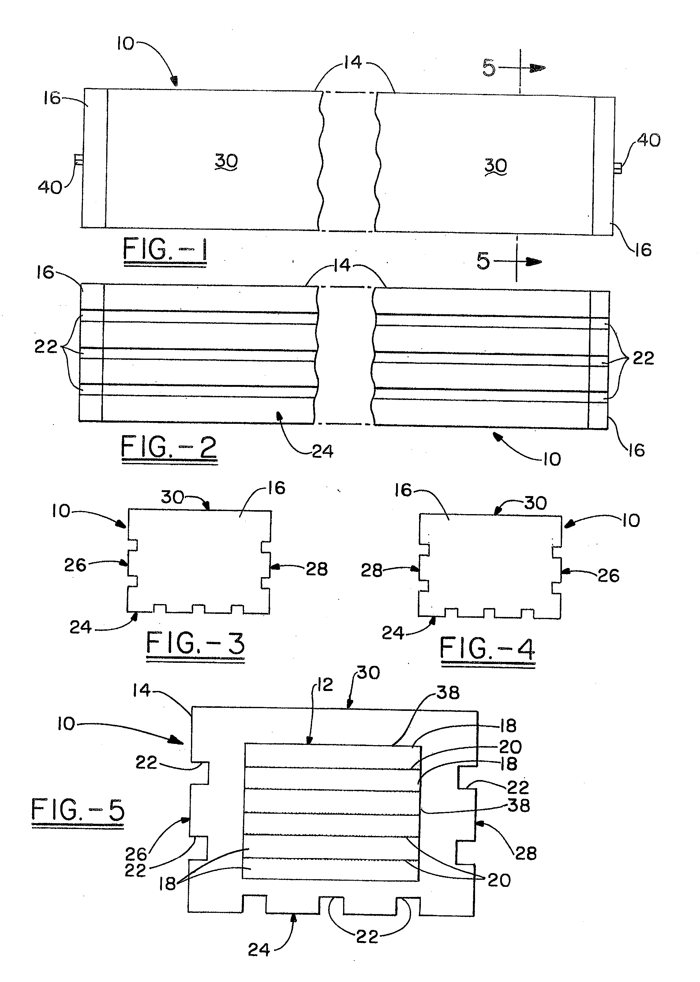
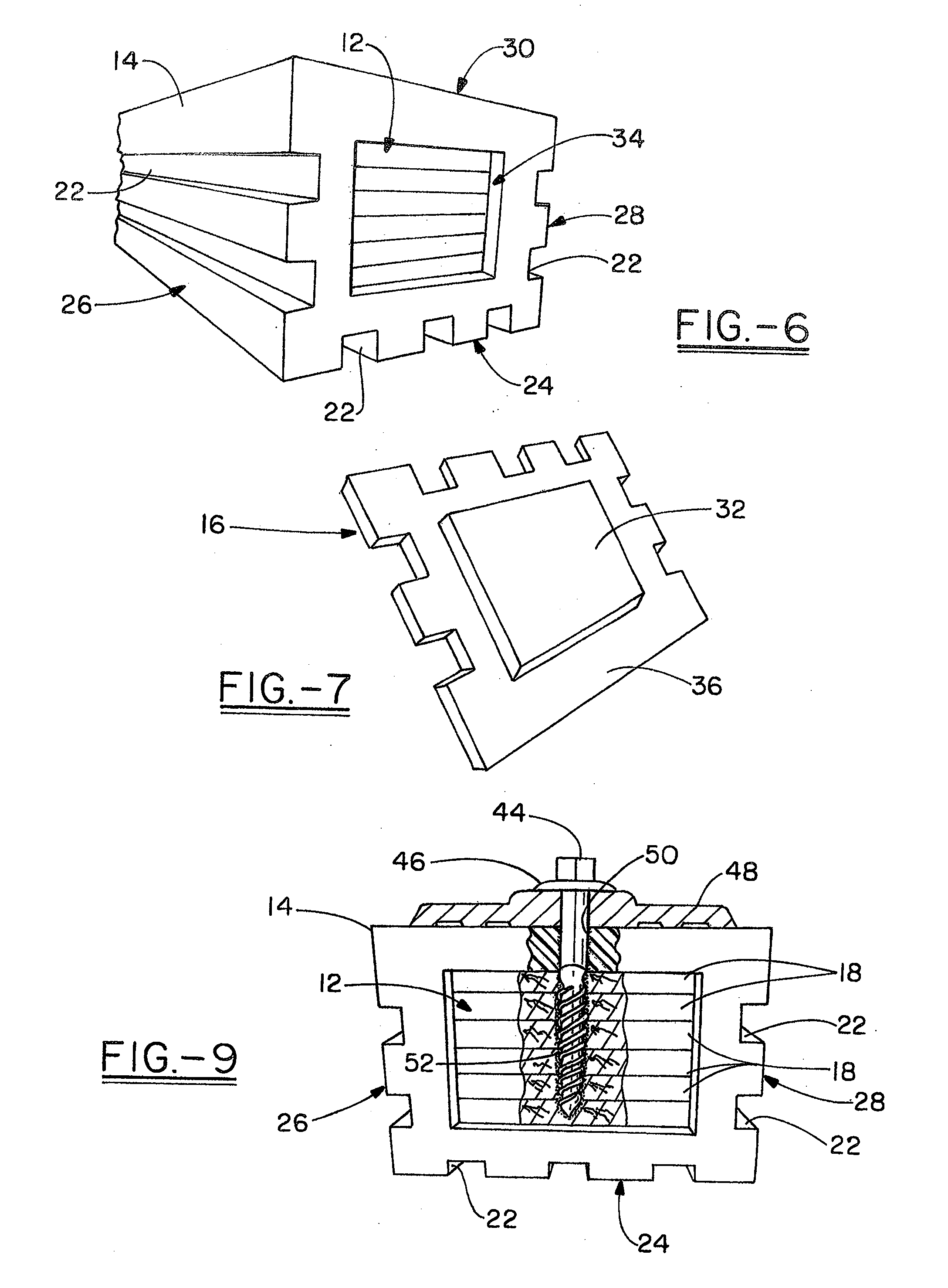
[0040]Referring now to the drawings, it can be seen that in the preferred embodiment the composite structural member of the invention, generally designated by reference number 10, includes a core 12, an outer layer 14, and end caps 16. The structural member of the invention is contemplated to be particularly useful for railroad ties, but the scope of the invention is not limited to use of the structure for that purpose, and encompasses any use to which the structure may prove to be suited.

[0041]Core 12 is preferably formed with a generally rectangular cross-sectional configuration, of a plurality of slats, planks or boards 18. Slats 18 are layered or stacked, with each slat in the interior of the stack in face-to-face contact with adjacent slats, and with their side edges and ends aligned. The slats are secured together with a specially formulated adhesive material 20 applied between each slat. In the preferred method of the invention, the selected numbers of slats used to make each...


PUM


Abstract

An encapsulated railroad tie structure and its method of manufacture. A core of laminated wood slats is inserted into an extruded sleeve of scrap tire rubber and polyurethane. A urethane adhesive laminates the wood slats together and serves as a lubricant and bonding agent for placement and secured engagement of the sleeve about the core. End caps are securely engaged to both the core and sleeve. The core may be provided with bores and grooves to receive sensors and conductors interconnected with a processor and transponder maintained in an end cap. The end cap also maintains a photovoltaic device and power source for the active elements of the railroad tie structure. The core may also be manufactured of a wood or other natural fiber giving the core a desired flex modulus to provide for better control and serviceability of associated rails and railway cars.

Description

CROSS REFERENCE TO RELATED APPLICATION[0001]This application is a continuation-in-part of U.S. patent application Ser. No. 12 / 649,921, filed on Dec. 30, 2009.TECHNICAL FIELD[0002]The present invention generally relates to composite structures, and in its preferred embodiments more specifically relates to a load bearing composite structure useful for railroad ties and other load bearing structural members, and particularly to railroad ties that can be manufactured to a particular flex modulus for better interaction with rail cars. Specifically, the disclosed invention also relates to railroad ties having associated data sensors, processors and transponders.BACKGROUND ART[0003]Railroad ties have traditionally been made of solid wood, typically hardwood that has been chemically treated with a preservative such as creosote to discourage insect attack and biological degradation. Treated solid wood ties, however, have a relatively short useful life span of five to fifteen years before the...

Claims


Application Information

Patent Timeline
IPC IPC(8): B61L25/00E01B3/00
CPCB61L1/02E01B3/46B61L29/22B61L27/0077B61L27/40E01B3/00E01B3/10
Inventor DJERF, TORBENEISENHUT, JOHN D.
Owner TJ TECH HLDG
Why Eureka
Try Eureka