Inspection system utilizing solid immersion lenses

a technology of immersion lens and inspection system, applied in the field of inspection system, can solve the problems of degrading sil imaging, difficult high-resolution observation, and conventional systems exhibit instability, and achieve the effects of easy stitching adjacent images, high-resolution images, and large field of view

Active Publication Date: 2012-04-19
INFRARED LAB
View PDF3 Cites 27 Cited by
  • Summary
  • Abstract
  • Description
  • Claims
  • Application Information

AI Technical Summary

Benefits of technology

[0034]In the typical applications of FA, a user will have a region in which a specific object of interest needs to be placed at an exact location within the detector field of view. With the use of a stage in which the SIL lens will focus the objective to the DUT, the mechanics of the present teachings will a

Problems solved by technology

Conventional systems exhibit instability with the landing of the SIL lens with respect to the silicon DUT.
However, due to normally occurring surface irregularities due to the preparation of the surface, the SIL will not properly couple to the DUT, greatly degrading SIL imaging.
DUT flatness is important, as gaps between the SIL lens and DUT, brought about by SIL lens tilt or sample preparation, produces aberrations and makes high resolution observation difficult.
In the above described conventional systems, the excessive force is typically produced by, among other factors, the lack of effective control of the angle between the solid immersion lens (SIL) and the device under test (DUT).
The rigidity is typically due to:a. conventional lens design attempts to constrain five degrees of motion of each lens with respect to the other (rotation about the chief ray is not controlled—axisymmetric assumption) This results in a rigidly fixed SIL lens, which has little angular compliance, andb. the spring rate of the “SIL holder” along the direction of the chief ray, as well as in the tip and tilt directions, is very difficult to reduce.
Backlash degrades image performance due to non-repeatable l

Method used


Image

  • Inspection system utilizing solid immersion lenses
  • Inspection system utilizing solid immersion lenses
  • Inspection system utilizing solid immersion lenses

Examples


Embodiment Construction

[0050]“Parfocality,” as used herein, refers to the target (such as the device under test) staying in focus when the lens combination is changed.

[0051]“Parcentricity,” as used herein, refers to an object in the center of the field staying in the center of the field no matter which objective is being used.

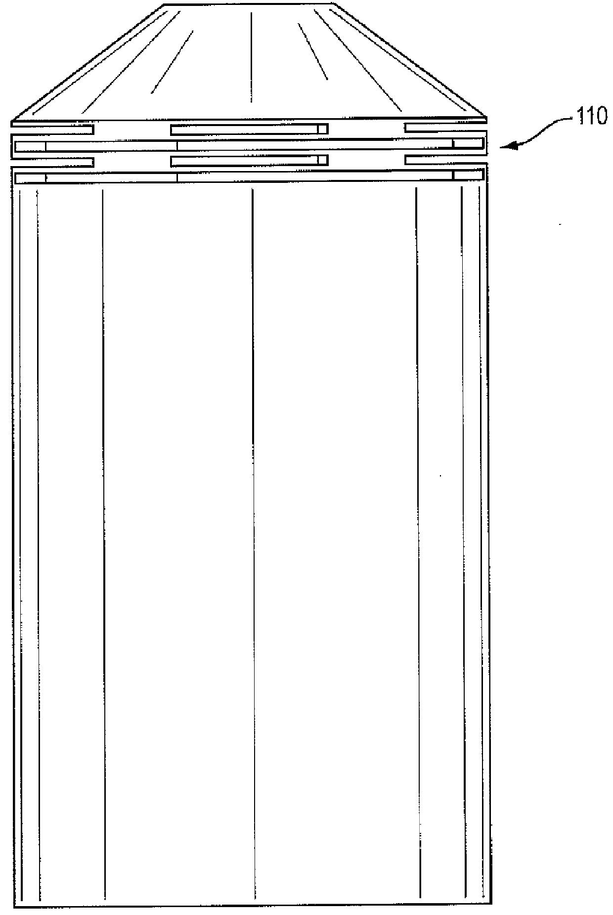
[0052]In one embodiment, the system of these teachings includes a solid immersion lens, the solid immersion lens being at least a portion of a hemisphere, a housing, the housing having one end, the solid immersion lens being mounted on the one end, the one end including a solid immersion lens receiving surface (also referred to as the housing bearing seat or the bearing seat); the solid immersion lens receiving surface being sized to receive the solid immersion lens and to allow solid immersion lens rotation with respect to the solid immersion lens receiving surface; and a top surface disposed a predetermined height away from the center of the hemisphere, the top surface having a sub...


PUM


Abstract

An inspection system including a lens. In one instance, the lens is a solid immersion lens. The inspection system includes a component or components for providing a self aligning solid immersion lens arrangement in order to allow at most a small distance between the solid immersion lens and a device under test and components or components for constraining a force exerted on the device under test. The inspection system may include a “purge” port, or a thermal isolation configuration or an anti-contamination component. The inspection system may include software and hardware to prevent crashing of the lens. The inspection system may also include a method for ensuring that various objective lenses can be replaced while maintaining the intended spacing between lenses.

Description

BACKGROUND[0001]The present teachings relate to an inspection system utilizing one or more Solid Immersion Lenses (SILs), the inspection system including silicon lenses, and a surrounding housing.[0002]High spatial resolution imaging, in conjunction with high collection efficiency, can be used in the examination and testing of particular sub-micron structures. The size reduction of these sub-micron structures have been following the prediction made by Gordon Moore in 1965, more commonly known as Moore's Law. Within the semiconductor industry, Moore's Law stated that the maximum number of transistors able to fit within a given area will double every two years. Since the optical numerical aperture is based on the index of refraction of the medium between the objective and sample and the collection angle of the objective, the highest numerical aperture (NA) achievable by an air lens is unity.[0003]This technology utilizes a hemispherical or cone shaped solid immersion lens (Hemi or Con...

Claims


Application Information

Patent Timeline
IPC IPC(8): G01N21/88G02B27/56G02B7/02
CPCG02B21/33
Inventor DOZOR, DAVID M.KIM, YULLINTUMIDAJSKI, KRISFANCHER, GARYSALVESTRINI, KENHOLT, DOUGLASDEWITT, JR., RON
Owner INFRARED LAB
Why Eureka
Try Eureka