Method for site specific energy capture optimization through modular rotor blade tip extension

a technology of modular rotor blades and energy capture, which is applied in the direction of machines/engines, mechanical equipment, final product manufacturing, etc., can solve the problems of over-design margin, and achieve the effects of increasing revenue and profit, increasing energy capture, and increasing energy captur

Inactive Publication Date: 2012-04-19
CLIPPER WINDPOWER INC
View PDF8 Cites 32 Cited by
  • Summary
  • Abstract
  • Description
  • Claims
  • Application Information

AI Technical Summary

Benefits of technology

[0015]In accordance with a further aspect of the disclosure, a joining method is provided for simple connection to and removal of the modular blade tips from a baseline blade during the manufacturing process or the site setup process.
[0016]Significant value is provided by the disclosed process through increased energy capture at a given site. For the owner / operator of a wind turbine, increased energy capture equates to increased revenue and profit.
[0017]This disclosure has the advantage that it increases energy capture at a given site by utilizing larger rotor diameters across the site, or at individual locations within a site array.
[0018]The modular method of the disclosure results in lower tooling costs, and allows for changing the blade lengths should on-site conditions change after on-site installation of the blades. An alternative approach is to capture more energy through longer blades by manufacturing a new blade design for each incremental increase in length for the given on-site conditions. This results in much higher tooling costs.

Problems solved by technology

This results in excess design margin in the machine design that can be leveraged by incrementally increasing the rotor diameter to the point at which the operational loads experienced by the machine will more fully utilize its structural capacity.

Method used


Image

  • Method for site specific energy capture optimization through modular rotor blade tip extension
  • Method for site specific energy capture optimization through modular rotor blade tip extension
  • Method for site specific energy capture optimization through modular rotor blade tip extension

Examples


Embodiment Construction

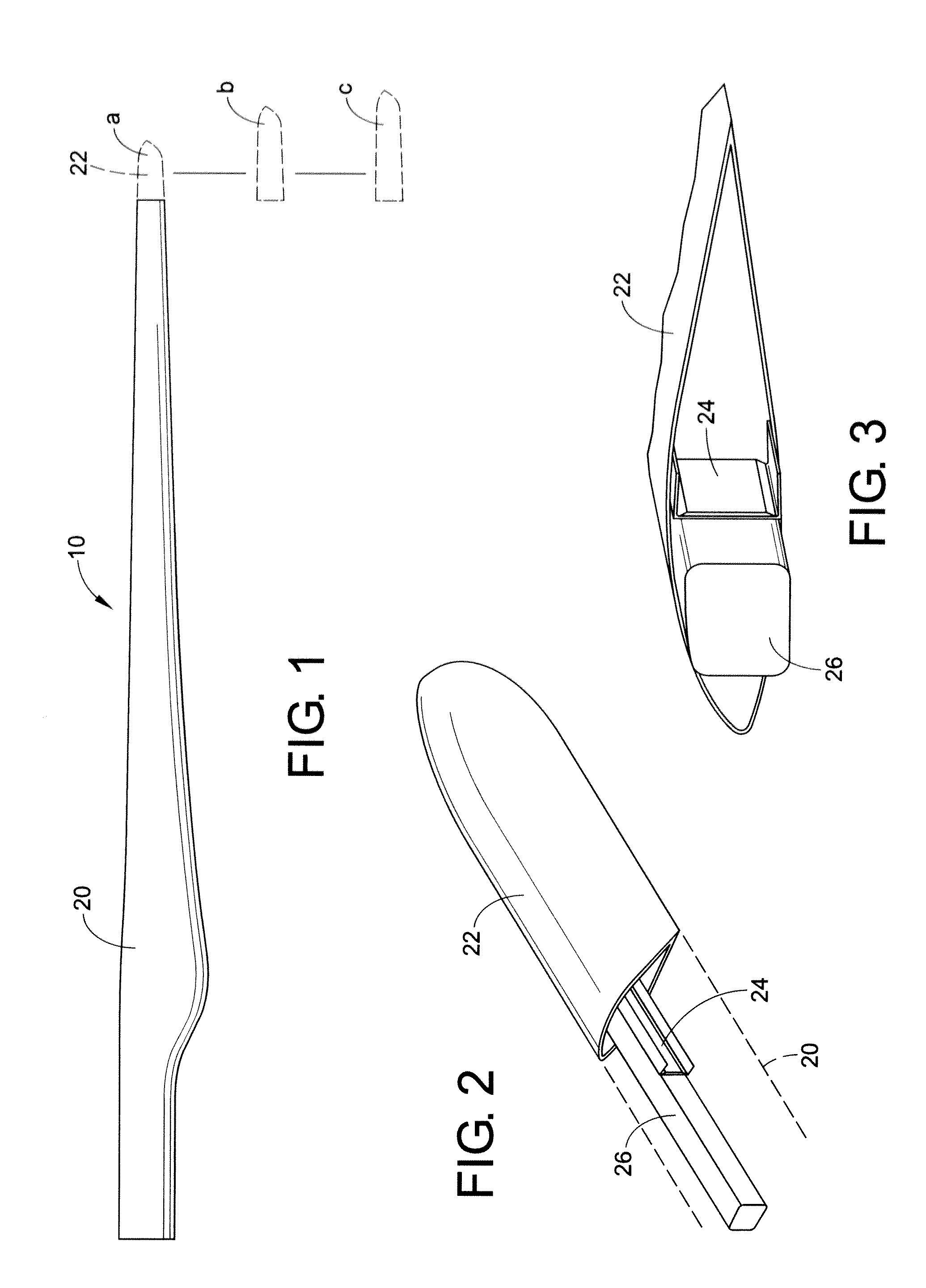
[0029]Referring to FIG. 1, it is a perspective view of a rotor blade 10 of the present disclosure comprising a main blade body 20 and a detachable outer aerodynamic extender blade tip 22, chosen from several blade lengths, such as three blade lengths, a, b, and c, illustrated by broken lines. A rotor has a root blade (base main blade 20) and an extender blade tip 22 resulting in a blade 10 of fixed length. The extender blade tip 22 provides a modular feature, which increases or decreases the rotor diameter depending upon which blade tip, a, b or c, is attached to the main blade section 10.

[0030]As to FIG. 2, it is a perspective view of an extender blade beam 24 of the extender blade 22 within the base blade 20. It shows one embodiment of a base blade beam 26 with the attachment end 24 of the extender blade beam attached to the base blade beam 26.

[0031]With reference to FIG. 3, it is a sectional view of the extender blade beam 24 of extender blade 22 and the base blade beam 26 of FIG...


PUM


Abstract

A power generating system wherein a turbine (34) is mounted on top of a tower (30) or tethered underwater. The turbine (34) includes a rotor having a main blade (20) connected to a rotor hub (40) and an extender blade tip (22, 22′) attached to the main blade (20). During manufacture, the optimum energy-capture is determined using site-specific conditions of one or more of air density, wind speed, extreme wind, wind shear, noise and turbulence intensity. The extender blade tip (22, 22′) is chosen from a number of extender blade tips having a length that is the closest to the determined optimum energy-capture. The chosen extender blade tip is attached to the main blade either during manufacture or on-site. Alternatively, a one piece blade is produced based on information determined from the site specific conditions. The tip of such one piece blade can be customized based on the information obtained.

Description

BACKGROUND[0001]This disclosure relates to electric power-generating devices, such as wind turbines and ocean current turbines, and more particularly to a structural support for a wind turbine blade which has a detachable outer aerodynamic blade tip, which can be replaced with a longer blade tip that increases the rotor diameter and captures more wind energy or a shorter blade tip to reduce wind energy exposure.[0002]Modern wind turbines are typically designed to a standard wind classification defining an average wind speed, turbulence intensity, extreme wind, and average air density. Current wind turbine design practice uses the wind classification to define extreme loads and fatigue loads that drive the design of the mechanical structure. However, wind turbines are typically deployed to sites or locations within an array of wind turbines at a particular site, which have lower average wind speeds, air density or turbulence intensities than that defined by the standard wind classifi...

Claims


Application Information

Patent Timeline
Patent Type & Authority Applications(United States)
IPC IPC(8): F04D27/00
CPCF03D1/001F03D1/0675Y02E10/728Y02E10/721F05B2240/313F03D13/10F05B2240/302Y02E10/72Y02P70/50F05B2240/307
Inventor CHRISTENSON, CRAIG LEONARDGLENN, BRIANKILS, OLEGATES, ROBERT H.NEMILA, THOMAS E.
Owner CLIPPER WINDPOWER INC
Why Eureka
Try Eureka