Honeycomb catalyst body and method for manufacturing honeycomb catalyst body

a technology of honeycomb and catalyst body, which is applied in the direction of physical/chemical process catalysts, paper/cardboard containers, separation processes, etc., can solve the problems of contaminant harmful to the environment and the human body

Inactive Publication Date: 2012-04-19
IBIDEN CO LTD
View PDF6 Cites 17 Cited by
  • Summary
  • Abstract
  • Description
  • Claims
  • Application Information

AI Technical Summary

Benefits of technology

[0015]According to one aspect of the present invention, a honeycomb catalyst body includes a honeycomb structure and a catalyst. The honeycomb structure includes a porous honeycomb fired body having at least one cell wall defining a plurality of cells extending along a longitudinal direction of the porous honeycomb fired body. The plurality of cells is provided in parallel with one another. The honeycomb fired body contains silicon carbide particles and a silica layer formed on a surface of each of the silicon carbide particles. The silica layer has a thickness of from about 5 nm to about 100 nm measured by X-ray photoelectron spectroscopy. The catalyst contains at least one of oxide ceramics and zeolite. The catalyst is provided on a surface of the silica layer. An amount of at least one of the oxide ceramics and the zeolite is about 50 g / L or more.
[0016]According to another aspect of the present invention, a method for manufacturing a honeycomb catalyst body includes: oxidizing a honeycomb structure including a porous honeycomb fired body by heating under an oxidative atmosphere at from about 700° C. to about 1100° C. for from about 1 hour to about 10 hours, the honeycomb fired body having at least one cell wall defining a plurality of cells extending along a longitudinal direction of the porous honeycomb fired body, the plurality of cells being provided in parallel with one another, the oxidizing of the honeycomb structure including forming a silica layer on a surface of each of silicon carbide particles contained in the honeycomb fired body, the silica layer having a thickness measured by X-ray photoelectron spectroscopy of from about 5 nm to about 100 nm; and treating the oxidized honeycomb structure with a supporting process so that a catalyst containing at least one of oxide ceramics and zeolite is provided on the oxidized honeycomb structure, an amount of at least one of the oxide ceramics and the zeolite being about 50 g / L or more.

Problems solved by technology

Recently, particulates (hereinafter, also referred to as PM) such as soot in exhaust gases discharged from internal combustion engines such as diesel engines have raised problems as contaminants harmful to the environment and the human body.
Further, there have been concerned about an influence on the environment and the human body by toxic gas components, such as CO, HC, and NOx, also contained in the exhaust gases.

Method used


Image

  • Honeycomb catalyst body and method for manufacturing honeycomb catalyst body
  • Honeycomb catalyst body and method for manufacturing honeycomb catalyst body
  • Honeycomb catalyst body and method for manufacturing honeycomb catalyst body

Examples


first embodiment

[0051]Now, a description is given with reference to drawings on a first embodiment that is one embodiment of a honeycomb catalyst body and a method for manufacturing a honeycomb catalyst body of the present invention.

[0052]First, a description is given on a honeycomb catalyst body according to the first embodiment of the present invention.

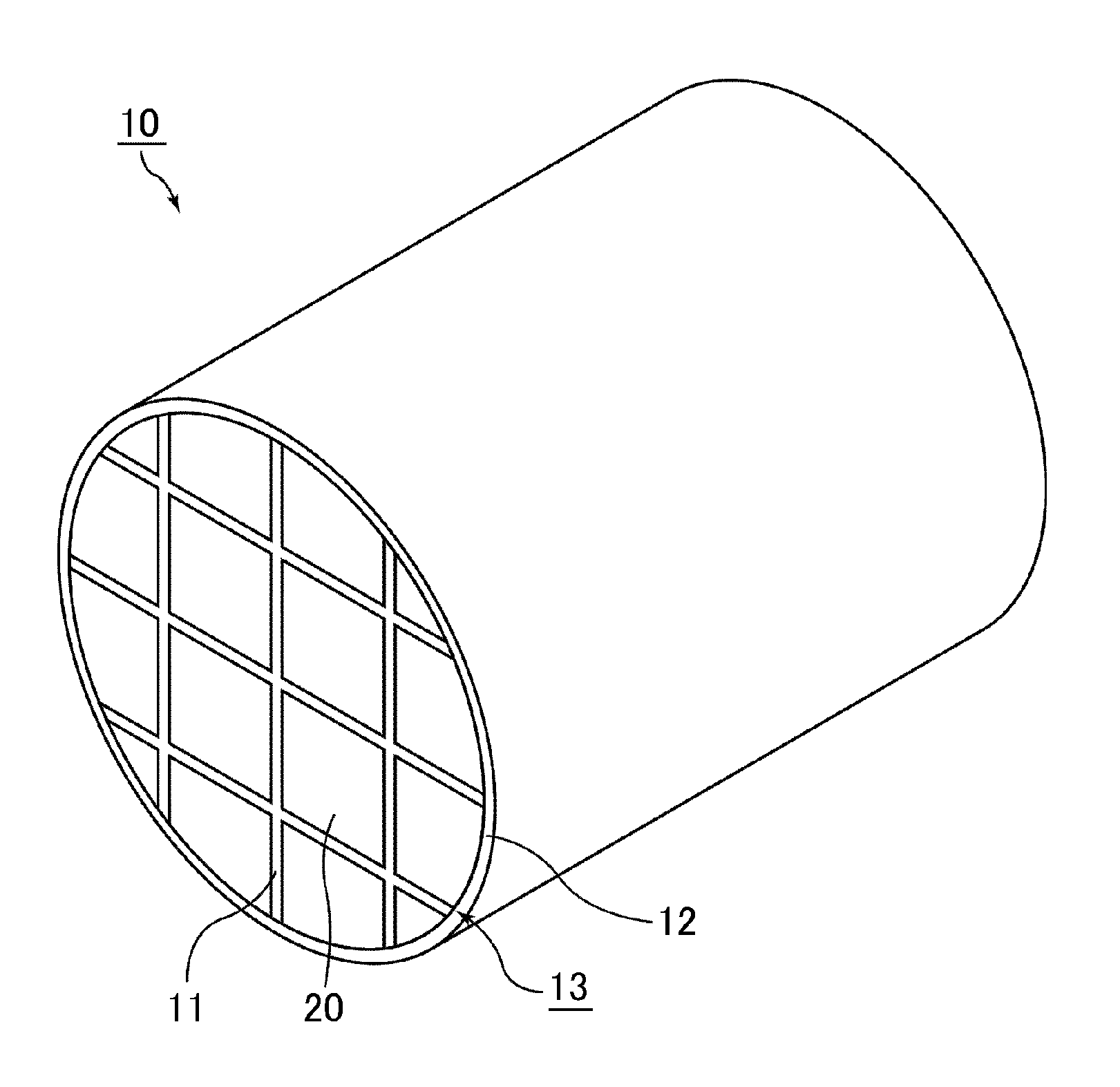
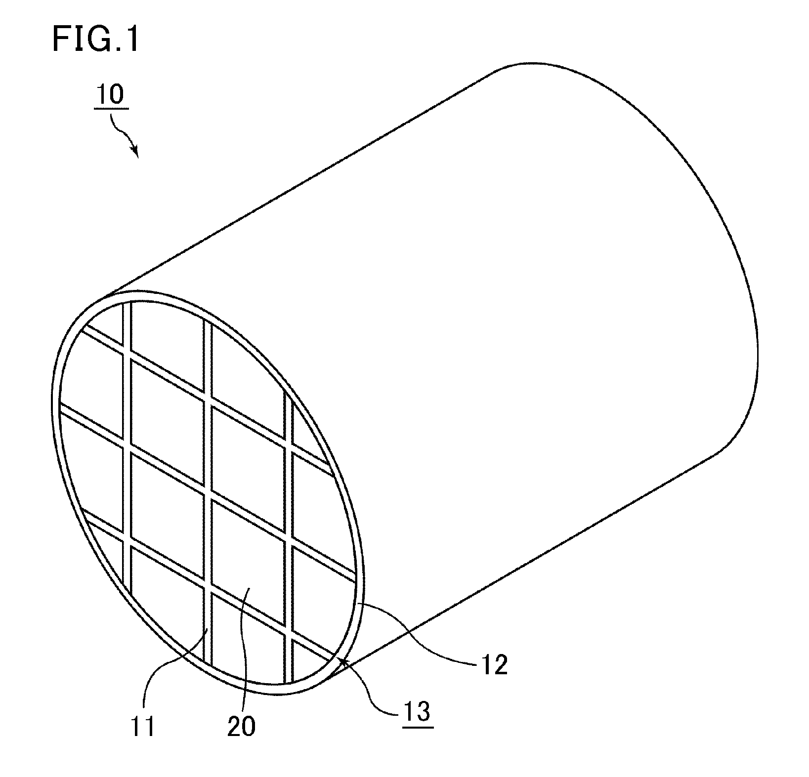
[0053]FIG. 1 is a schematic perspective view illustrating one example of a honeycomb structure configuring a honeycomb catalyst body of the first embodiment of the present invention.

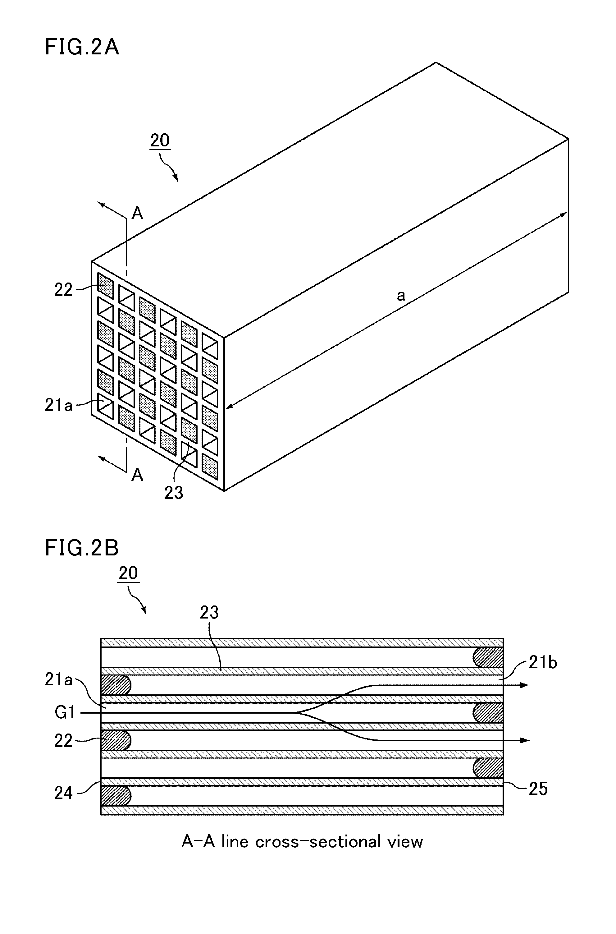
[0054]FIG. 2A is a schematic perspective view illustrating one example of a honeycomb fired body configuring the honeycomb structure illustrated in FIG. 1. FIG. 2B is an A-A line cross-sectional view illustrating the honeycomb fired body in FIG. 2A.

[0055]In a honeycomb structure 10 illustrated in FIG. 1, a plurality of porous honeycomb fired bodies 20 mainly made of silicon carbide particles are bound to one another via an adhesive layer 11 therebetween to form a cerami...

example 1

(Manufacture of Honeycomb Catalyst Body)

[0137](1) Manufacturing Process of Honeycomb Structure

[0138]An amount of 52.8% by weight of a silicon carbide coarse powder having an average particle size of 22 μm and 22.6% by weight of a silicon carbide fine powder having an average particle size of 0.5 μm were mixed. To the resulting mixture, 2.1% by weight of an acrylic resin, 4.6% by weight of an organic binder (methylcellulose), 2.8% by weight of a lubricant (UNILUB, manufactured by NOF Corporation), 1.3% by weight of glycerin, and 13.8% by weight of water were added, and then kneaded to prepare a wet mixture. The obtained wet mixture was extrusion-molded, and an extrusion-molded body was cut to manufacture a raw honeycomb molded body having the same shape as that illustrated in FIGS. 2A and 2B and having cells not plugged.

[0139]This raw honeycomb molded body was dried by using a microwave drying apparatus to manufacture a dried honeycomb molded body. Then, predetermined cells of the dr...

examples 2 to 6

[0154]Honeycomb catalyst bodies were manufactured in the same manner as in Example 1, except that the heat treatment temperature and the heat treatment time in the oxidation process were changed as shown in Table 1.

[0155]The heat treatment temperature and the heat treatment time in Examples 2 to 6 were 900° C. for 10 hours, 1000° C. for 3 hours, 1100° C. for 1 hour, 1100° C. for 3 hours, and 1100° C. for 4 hours, respectively.


PUM

PropertyMeasurementUnit
thicknessaaaaaaaaaa
thicknessaaaaaaaaaa
particle sizeaaaaaaaaaa

Abstract

A honeycomb catalyst body includes a honeycomb structure and a catalyst. The honeycomb structure includes a porous honeycomb fired body having at least one cell wall defining a plurality of cells extending along a longitudinal direction of the porous honeycomb fired body. The plurality of cells is provided in parallel with one another. The honeycomb fired body contains silicon carbide particles and a silica layer formed on a surface of each of the silicon carbide particles. The silica layer has a thickness of from about 5 nm to about 100 nm measured by X-ray photoelectron spectroscopy. The catalyst contains at least one of oxide ceramics and zeolite. The catalyst is provided on a surface of the silica layer. An amount of at least one of the oxide ceramics and the zeolite is about 50 g/L or more.

Description

CROSS-REFERENCE TO RELATED APPLICATIONS[0001]The present application claims priority under 35 U.S.C. §119 to Japanese Patent Application No. 2010-230194, filed on Oct. 13, 2010, the contents of which are incorporated herein by reference in their entirety.BACKGROUND OF THE INVENTION[0002]1. Field of the Invention[0003]The present invention relates to a honeycomb catalyst body and a method for manufacturing a honeycomb catalyst body.[0004]2. Discussion of the Background[0005]Recently, particulates (hereinafter, also referred to as PM) such as soot in exhaust gases discharged from internal combustion engines such as diesel engines have raised problems as contaminants harmful to the environment and the human body. Further, there have been concerned about an influence on the environment and the human body by toxic gas components, such as CO, HC, and NOx, also contained in the exhaust gases.[0006]To capture PM and convert toxic gas components in exhaust gases, various honeycomb catalyst b...

Claims


Application Information

Patent Timeline
Patent Type & Authority Applications(United States)
IPC IPC(8): B01D53/86B32B37/12B05D3/00B32B38/10B05D5/00B32B37/14B82Y30/00B82Y40/00
CPCB01D53/9418Y10T156/10B01D2255/20761B01D2255/30B01D2255/50B01D2255/9155B01J21/08B01J27/224B01J29/072B01J35/002B01J35/023B01J35/04B01J35/1076B01J37/0009B01J37/0217B01J37/08B01J37/14Y10T156/1052B01D2251/2067
Inventor IWAKURA, MISAKOOTA, KOHEI
Owner IBIDEN CO LTD
Why Eureka
Try Eureka