Infrared light reflector, infrared light reflecting laminated glass, and laminated glass and laminate have cholesteric liquid crystal layers

Inactive Publication Date: 2012-04-19
FUJIFILM CORP
View PDF10 Cites 25 Cited by
  • Summary
  • Abstract
  • Description
  • Claims
  • Application Information

AI Technical Summary

Benefits of technology

[0050]According to the first invention, it is possible to improve the reflectivity characteristic of an infrared-light reflective plate that has a plurality of light-reflective layers each formed of fixed cholesteric liquid-crystal, without indispensable use of a 2J2 plate therein. And according to the invention, it is possible to improve the selective reflectivity characteristic of t

Problems solved by technology

The special metallic film formed through vacuum deposition is extremely excellent in reflectivity, but the vacuum process is nonproductive and its production cost is high.
In addition, when the metallic film is used, it also blocks electromagnetic waves; and therefore in use in mobile telephones and the like, the metallic film may causes radio disturbance; or when used in automobiles, there may occur a problem in that ETC (electronic toll collection) could not be used.
The metallic fine particles-containing film is excellent in visible light transmittance but has a low reflectivity to light falling within a wavelength range of from 700 to 1200 nm that significantly participates in heat shielding, and therefore has a problem in that its heat-shielding capability could not be enhanced.
Use of an infrared-absorbing dye may low

Method used


Image

  • Infrared light reflector, infrared light reflecting laminated glass, and laminated glass and laminate have cholesteric liquid crystal layers
  • Infrared light reflector, infrared light reflecting laminated glass, and laminated glass and laminate have cholesteric liquid crystal layers
  • Infrared light reflector, infrared light reflecting laminated glass, and laminated glass and laminate have cholesteric liquid crystal layers

Examples


example 11

(1) Example 11

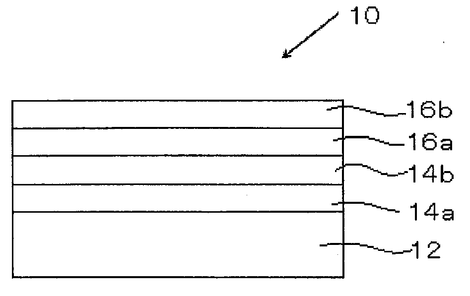
[0150]As a substrate, polyethylene terephthalate film (occasionally, referred to as “PET film”) having a thickness of 188 micro meters was prepared. The PET film, “FPA14-188” manufactured by FUJIFILM, had, on the surface and the rear-surface thereof respectively, an undercoat layer formed of urethane resin and an undercoat layer formed of acrylic resin.

[0151]Coating liquid (A) used in the above-described examples was applied to a surface of the substrate, dried, and then cured to form a cholesteric liquid crystal layer.

[0152]Next, Coating Liquid 1 having the following formulation was prepared. The coating liquid was applied to the surface of the cholesteric liquid crystal layer by using a bar so that the thickness of the dried layer was 2 micro meters, and then dried at 150 degrees Celsius for 7 minutes, thereby to form an easy-adhesion layer. In this way, Laminate 11 having the easy-adhesion layer was obtained.

[0153]Coating Liquid 1 for Easy-Adhesion Layer

Methoxy prop...

example 12

(2) Example 12

[0155]Coating Liquid 2 having the following formulation was prepaed.

[0156]Coating Liquid 2 for Easy-Adhesion Layer

Methoxy propyl acetate (PGMEA)100 parts by mass Ultraviolet absorber (Tinuvin 326 (by Ciba Japan))2.5 parts by massHALS Tinuvin 152 (by Ciba Japan)2.5 parts by massPolyvinyl butyral resin (“B1776” 10 parts by massmanufactured by ChangChun Group, Taiwan)

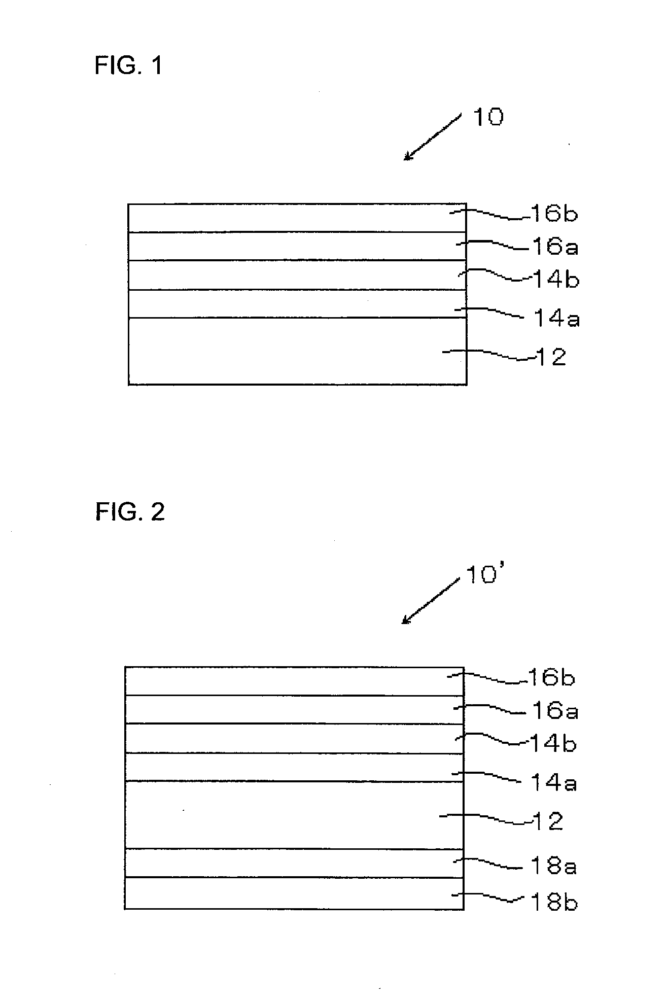
[0157]Laminate 12 was prepared in the same manner as Example 11, except that Coating Liquid 2 was used in place of Coating Liquid 1. Furthermore, a laminated glass was prepared in the same manner as Example 11, except that Laminate 12 was used in place of Laminate 11.


PUM

PropertyMeasurementUnit
Nanoscale particle sizeaaaaaaaaaa
Transmittivityaaaaaaaaaa

Abstract

To provide an infrared-light reflective plate having improved selective reflectivity characteristics, there is provided an infrared-light reflective plate reflects an infrared-light of equal to or longer than 700 nm including a substrate, and, on at least one of surfaces of the substrate, at least four light-reflective layers, X1, X2, X3 and X4, formed of a fixed cholesteric liquid crystal phase, and disposed in this order from the substrate, wherein the reflection center wavelengths of the light-reflective layers X1 and X2 are same with each other and are λ1 (nm), and the two layers reflect circularly-polarized light in opposite directions; the reflection center wavelengths of the light-reflective layers X3 and X4 are same with each other and are λ2 (nm), and the two layers reflect circularly-polarized light in opposite directions; and λ12 is satisfied.

Description

TECHNICAL FIELD[0001]The present invention relates to an infrared-light reflective plate with plural light reflective layers formed of a fixed cholesteric liquid crystal phase, mainly for use for heat shield for windows of building structures, vehicles, etc, and relates also to an infrared-light reflective laminated glass using it. The present invention relates also to a laminate having a cholesteric liquid crystal layer, and a laminated glass having it.BACKGROUND ART[0002]With the recent increase in interest in environment and energy-related issues, the needs for energy-saving industrial products are increasing; and as one of them, glass and film are desired that are effective for heat shield for windowpanes for houses, automobiles, etc., or that is, effective for reducing heat load due to sunlight. For reducing heat load due to sunlight, it is necessary to prevent transmission of sunlight rays falling within any of the visible range or the infrared range of the sunlight spectrum.[...

Claims


Application Information

Patent Timeline
IPC IPC(8): G02B5/20C09J7/02B32B7/12
CPCB32B17/10Y10T428/2848B32B17/10458B32B17/10761B32B17/10788G02B1/04G02B5/0841G02B5/0866G02B5/208G02B5/3016B32B17/10036C08L101/12B32B2367/00B32B17/10005
Inventor OKI, KAZUHIROICHIHASHI, MITSUYOSHIYAMADA, HITOSHI
Owner FUJIFILM CORP
Why Eureka
Try Eureka