
Synchronising a communications device

Active Publication Date: 2012-04-26
ADVANCED MICRO DEVICES INC +1
View PDF16 Cites 9 Cited by
  • Summary
  • Abstract
  • Description
  • Claims
  • Application Information

AI Technical Summary

Benefits of technology

[0013]The present method is useful in communication systems where a receiving device has to synchronise with a transmitting device, such as its frequency and / or timing. By receiving the beacon signal at a first frequency that is substantially less than the second frequency, the beacon signal can be more reliably received by the receiving device due to substantially lower path loss experienced by the beacon signal at the first frequency when compared to that of the data signal at the higher second frequency. Advantageously, the present method lowers total power consumption at the receiving device due to lower current drain in transmitting and receiving a beacon signal. For portable devices, lower power consumption translates into higher battery life and stand-by time, and throughput.

Problems solved by technology

While high-gain directional antennas work well for fixed point-to-point communications, they create problems when the stations or nodes are portable or mobile.
The hidden node / network is a typical problem, where a network is composed of two or more connected nodes.
However, the fact that both the transmitter and receiver antennas are highly directional means that the new node can only detect an existing node / network if their antenna directions happen to be aligned by chance.
As a result, the probability of missing the detection of an existing node / network is very high.
If a new node misses the detection of the existing nodes on the channel, the new node will either miss the opportunity to join the existing nodes or the new node will use the channel and cause interference for the others.
Because each node in the network uses highly directional antennas, effective broadcast and multicast schemes cannot be applied.
This solution is however not power efficient.
Another problem is that it is very hard for a new node to become synchronized to the existing nodes in time and frequency.

Method used


Image

  • Synchronising a communications device
  • Synchronising a communications device
  • Synchronising a communications device

Examples


Embodiment Construction

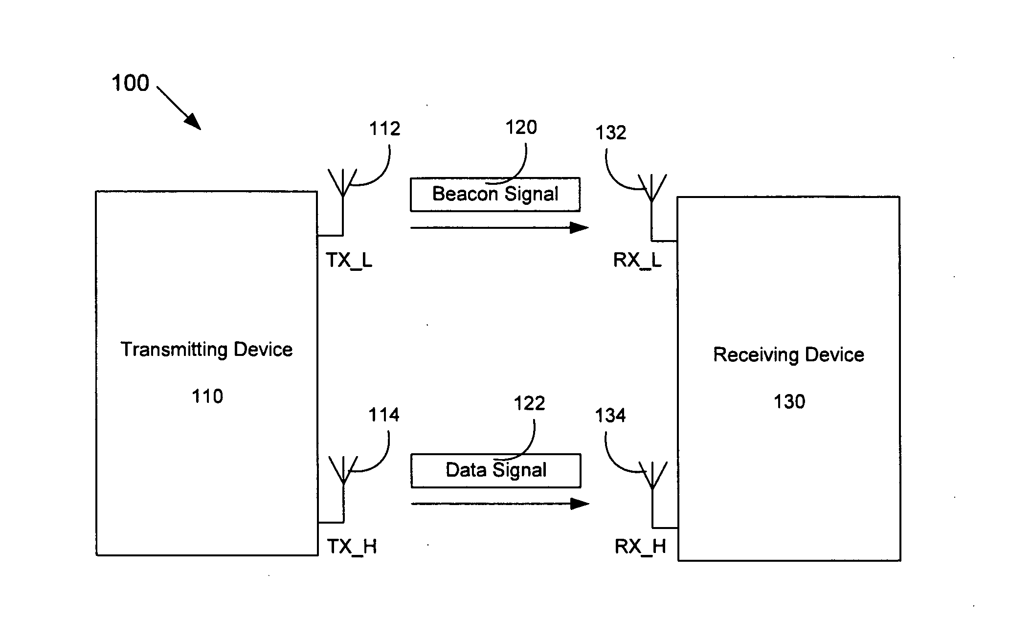
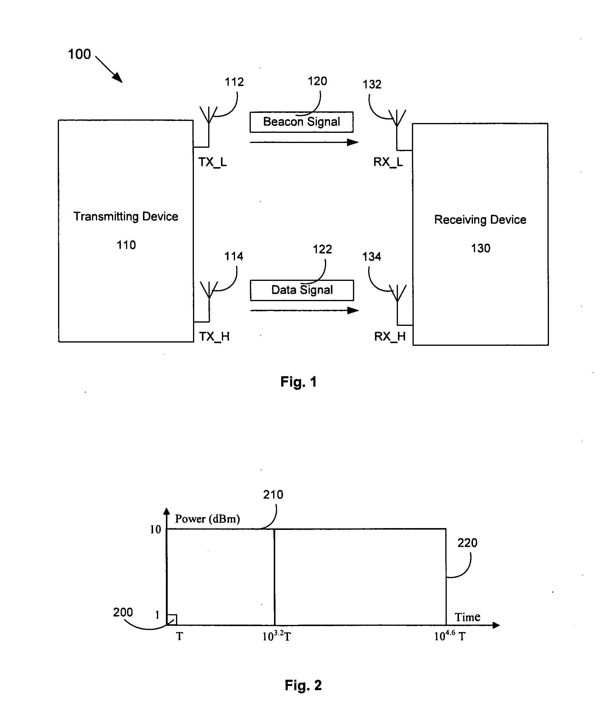
[0038]Referring first to FIG. 1, the system 100 comprises a first communications device 110 and a second communications device 130 operable to communicate with each other in a wireless communications network.

[0039]The devices 110 and 130 may be a mobile phone, a personal digital assistant (PDA) device, a desktop computer, a laptop computer or a tablet computer. The network may be a Institute of Electrical and Electronics Engineers (IEEE) 802.11 wireless network using wireless standards such as 802.11a, 11b, 11g, or 11ad. The specifications of IEEE 802.11 can be found, for example, on the IEEE Standards website at http: / / standards.ieee.org / getieee802 / 802.11.html, and are incorporated herein by reference.

[0040]In one example, the first communications device 110 is a transmitting device that wishes to transmit data signals to the second communications device 130, which is the receiving device. While not shown, the second communications device 130 may also be a transmitting device and v...


PUM


Abstract

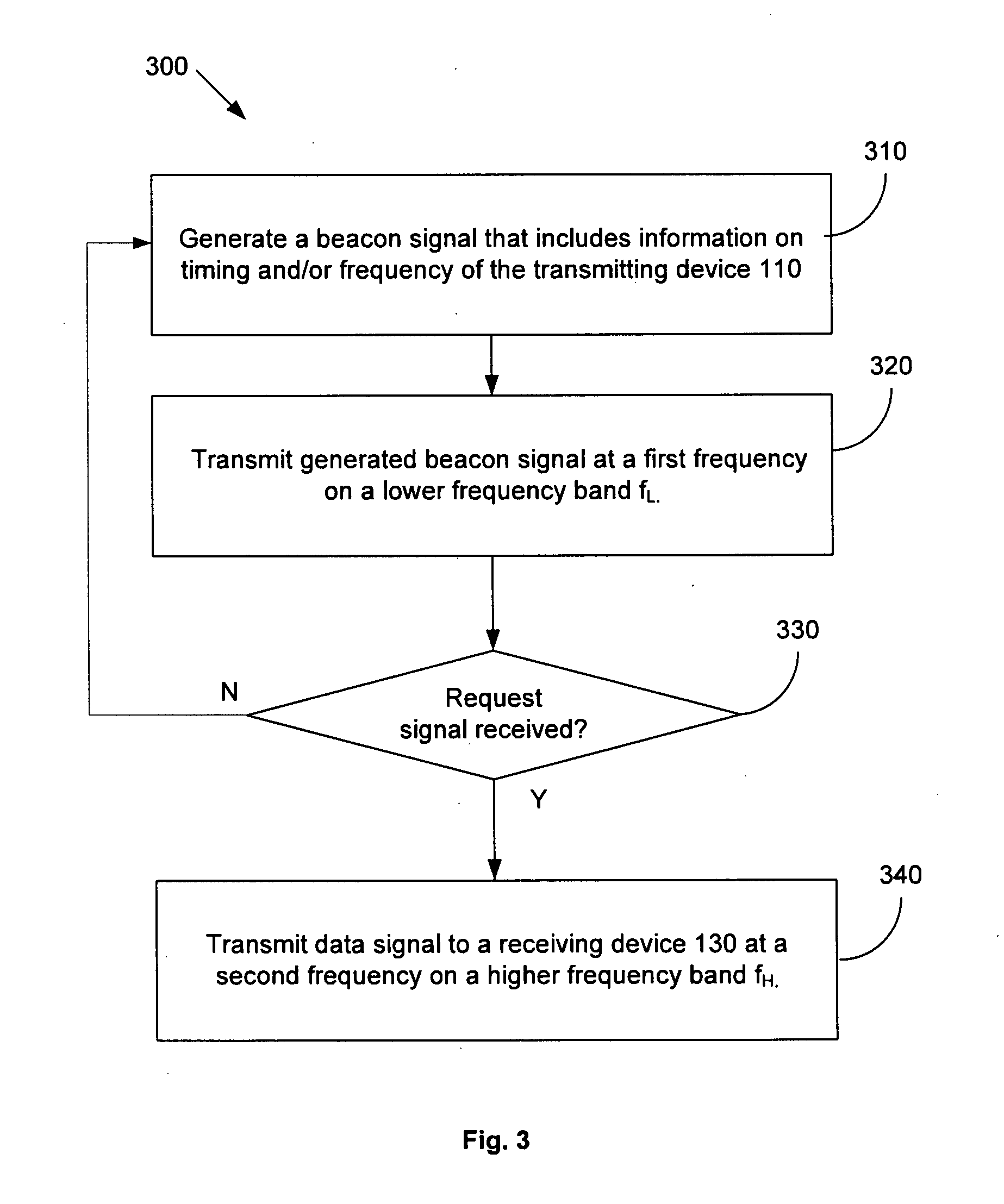
In one aspect, the method of synchronising a communications device in a wireless communications network comprises receiving a beacon signal at a first frequency; and receiving a data signal at a second frequency, the beacon signal being used to synchronise reception of the data signal. In another aspect, the method comprises transmitting a beacon signal at a first frequency and transmitting a data signal at a second frequency, the beacon signal being useable to synchronise reception of the data signal. The first frequency is substantially less than the second frequency such that the beacon signal experiences substantially different frequency-dependent propagation effects to the data signal.

Description

TECHNICAL FIELD[0001]The present invention relates to wireless data communications, and in particular to methods of synchronising a communications device in a wireless communications network, a receiving device, a transmitting device, a wireless communications system comprising the receiving device and the transmitting device, and computer program to implement the method.BACKGROUND OF THE INVENTION[0002]When a radio frequency (RF) signal propagates from a transmitter (TX) through a transmission media to the receiver (RX), the signal strength is reduced due to path loss. The path loss is proportional to fL, where f is the frequency of the signal and L is an environment-dependent parameter. In a practical non-line-of-sight (NLOS) environment, the parameter L is normally between 2 and 4. This physical law suggests that the higher the operating frequency is, the higher its path loss is within the same operating range. This means that more energy per information bit has to be radiated, c...

Claims


Application Information

Patent Timeline
IPC IPC(8): H04W56/00
CPCH04W56/0085H04L7/0008
Inventor LI, YUNXIN
Owner ADVANCED MICRO DEVICES INC
Learn More