Disc for an agricultural implement

a technology of agricultural implements and discs, which is applied in the direction of disc wheels, ploughs, planting, etc., can solve the problems of insufficient strength and impregnability of bearings, insufficient compactness of bearings, and insufficient construction height of bearings viewed in the direction of their central axis

a technology of agricultural implements and discs, which is applied in the direction of disc wheels, ploughs, planting, etc., can solve the problems of insufficient strength and impregnability of bearings, insufficient compactness of bearings, and insufficient construction height of bearings viewed in the direction of their central axis

US20120103642A1Active Publication Date: 2012-05-03VADERSTAD HLDG

Image

  • Disc for an agricultural implement
  • Disc for an agricultural implement
  • Disc for an agricultural implement

Examples


Embodiment Construction

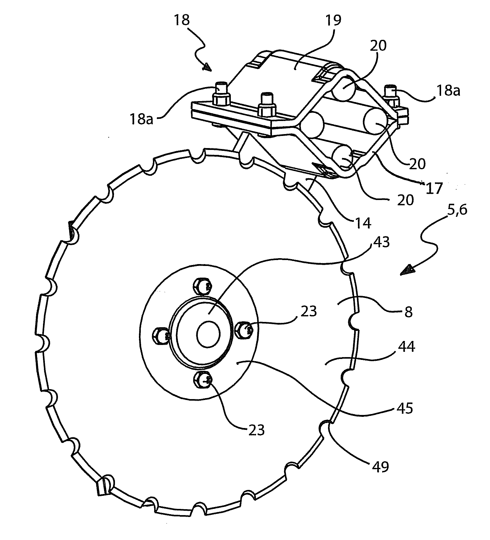
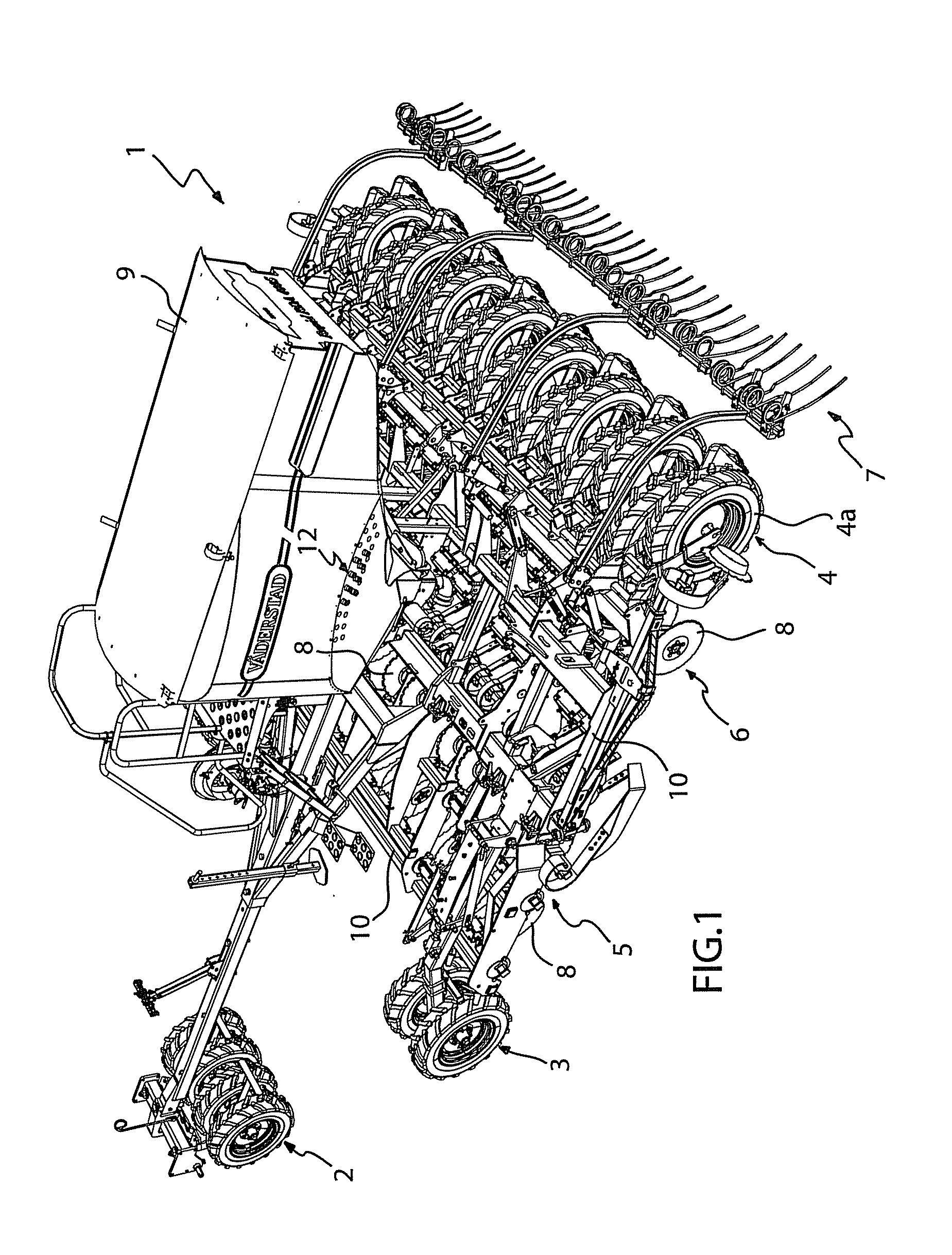
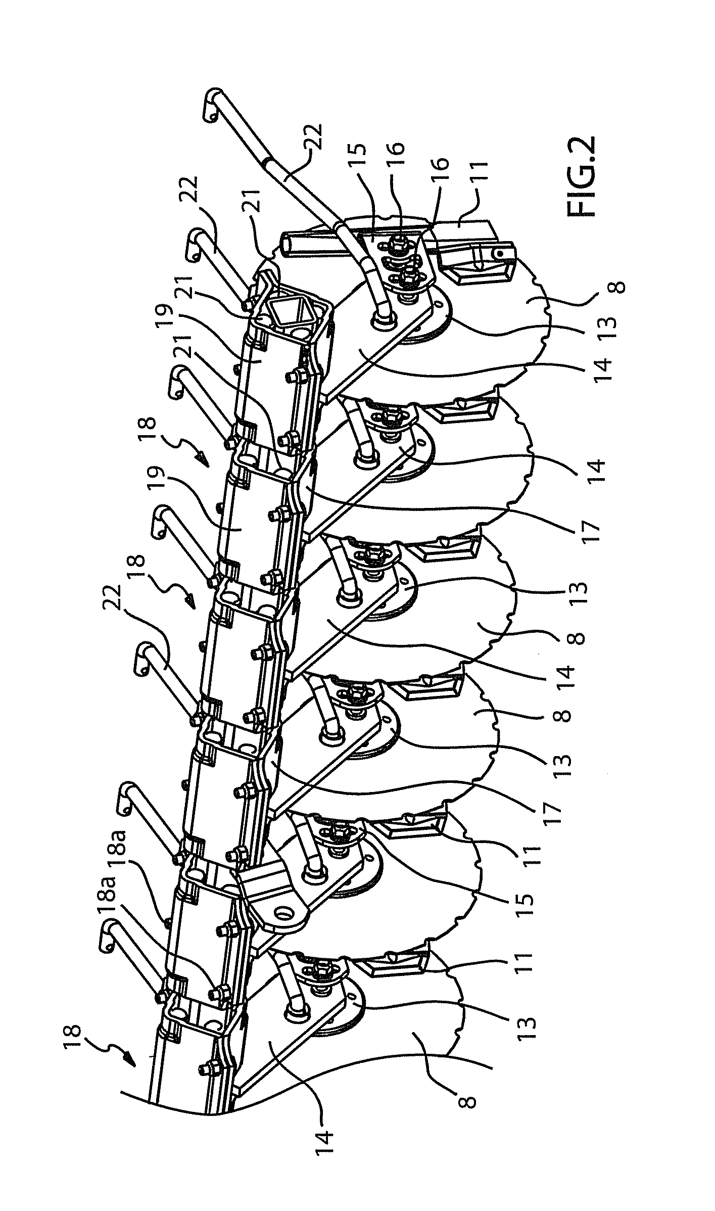
[0017]FIG. 1 shows an agricultural implement 1, which can be drawn by a not shown tractor. Instead of a tractor, the agricultural implement 1 can be propelled forward in other known ways. The agricultural implement 1 is here a seed drill and has wheel groups 2, 3, 4 and is provided with at least two sets of soil cultivating tools in a form including two fore rows of freely rotating disc aggregates 5 for soil cultivation and also incorporation of straw, and two rear rows of rotating disc aggregates 6 for the creation of seed furrows, plus a rear following harrow assemblage 7. Both sets of freely rotating disc aggregates 5, 6 can carry discs 8 according to the invention. The discs in the rows of disc aggregates 5 or 6 can be of different designs. The seed drill shown in FIG. 1 is only an exemplified embodiment for illustrative purposes and does not restrict the use of discs 8 according to the invention. A hopper 9 for seed and / or fertiliser is arranged on the frame 10 of the agricultu...


PUM


Abstract

The invention refers to a disc (8) for an agricultural implement (1) comprising an annular, outside a predetermined centre diameter (D) defined, soil-cultivating portion (44), a central, inside a predetermined centre diameter (d) defined, dish-shaped portion (43), with a boss-receiving, inner side and between these portions an existing, annular connection portion (45) with fastening screw holes (46). The connection portion (45) is a truncated conical portion, the inner mantle surface of which is mainly straight or double-bowed with the convex side facing said inner side and a line through the opening plane in the hole opening of each fastening screw hole on said inner side forms an angle α with a plane that is perpendicular to the centre line of the disc, wherein the angle α is 5°-10°.

Description

BACKGROUND OF THE INVENTION[0001]It has long been known to use different forms of discs in agricultural implements and often these discs work at an angle in order to till the soil in the desired way. The bearings have often been a weak point, since they are heavily loaded, and in addition they are difficult to build sufficiently impregnable. It is often difficult to manufacture a bearing with sufficient strength and impregnability that is still sufficiently compact. Often the construction height of the bearing viewed in the direction of its central axis has become too great. It has also been shown to be practically difficult to achieve a disc with hub or boss with small axial construction height. The axial extension is therefore often a problem. It is natural for it to be easier to make a sufficiently strong and impregnable bearing if it is allowed to increase in length or height. Furthermore, the discs are subjected to heavy wear and they are therefore commonly made from high-class...

Claims


Application Information

Patent Timeline
03 May 2012
Publication
US20120103642A1
IPC
A01B15/16; A01B23/06
CPC
A01C5/064; A01B23/06; A01B15/16; A01B71/04; B60B3/16
Inventors
STARK, CRISTER