Crude oil desulfurization

a crude oil and desulfurization technology, applied in chemical refining, non-metal refining, chemical refining, etc., can solve the problems of increasing increasing the cost of catalyst/desulfurizing agent, and increasing the use of low sulfur crude oil. , to achieve the effect of reducing the use of catalyst/desulfurizing agent, reducing the overall cost, and increasing the fluid throughpu

Active Publication Date: 2012-05-10
HRD CORP +1
View PDF3 Cites 11 Cited by
  • Summary
  • Abstract
  • Description
  • Claims
  • Application Information

AI Technical Summary

Benefits of technology

[0024]Certain embodiments of the above-described methods or systems potentially provide overall cost reduction by providing for reduced catalyst / desulfurizing agent usage, permitting increased fluid throughput, permitting operation at lower temperature and / or pressure, and / or reducing capital and / or operating costs. These and other embodiments and potential advantages will be apparent in the following detailed description and drawings.

Problems solved by technology

Natural fossil fuels, such as crude oil and natural gas, that contain a substantial concentration of sulfur compounds, such as hydrogen sulfide, sulfur dioxide, and mercaptans, are referred to as ‘sour.’ Sulfur compounds may evolve from fossil fuels over time and the evolution of these compounds produces significant environmental and safety issues.
There is an ever-increasing shortage of naturally-occurring low sulfur crude oil.
Not only does the evolution of sulfur compounds from crude oil produce significant environmental and safety issues, these compounds may also attack metal components of the oil well, as well as pipelines and storage tanks and downstream refinery apparatus.
This attack causes corrosion and / or brittleness of the metal components.
Sulfur removal typically comprises utilization of various desulfurization processes, often requiring extreme operating conditions, and incorporation of expensive equipment, often associated with high maintenance costs.

Method used


Image

  • Crude oil desulfurization
  • Crude oil desulfurization
  • Crude oil desulfurization

Examples


Embodiment Construction

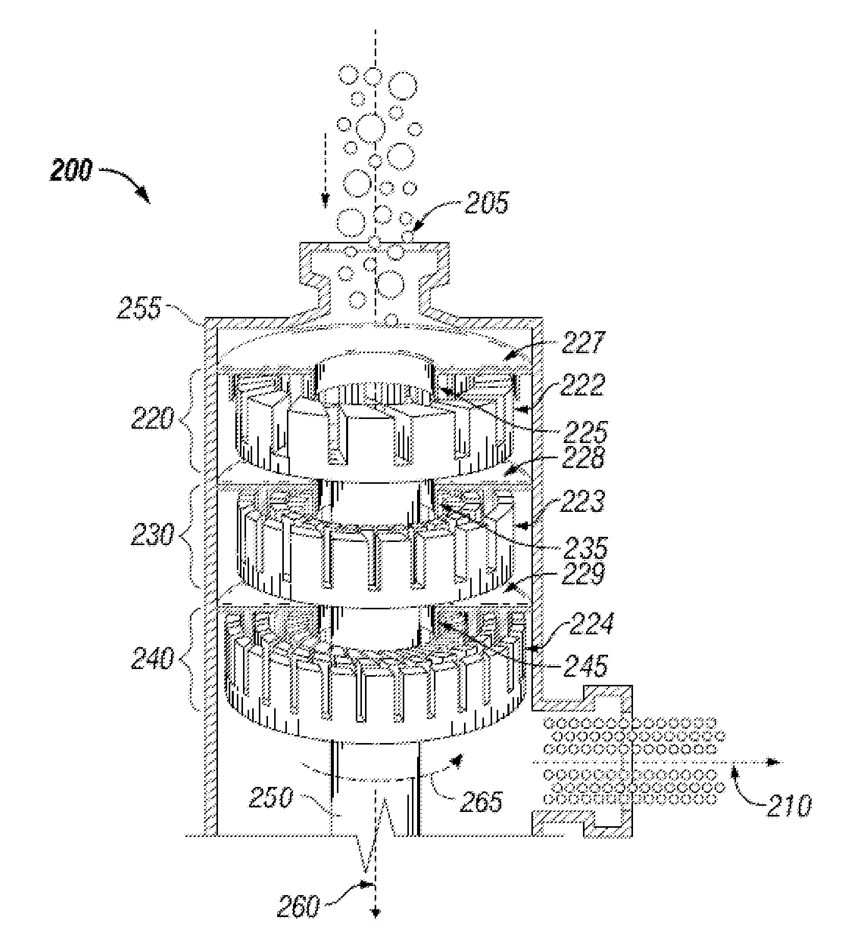
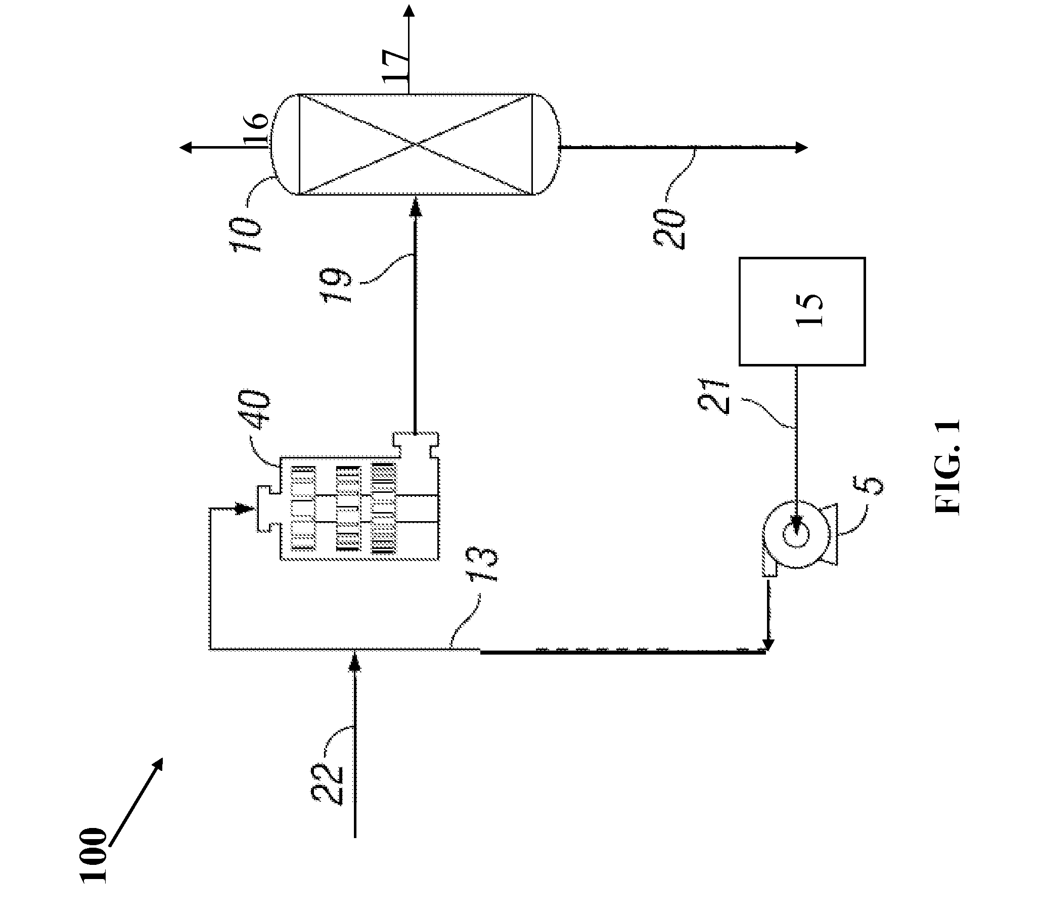
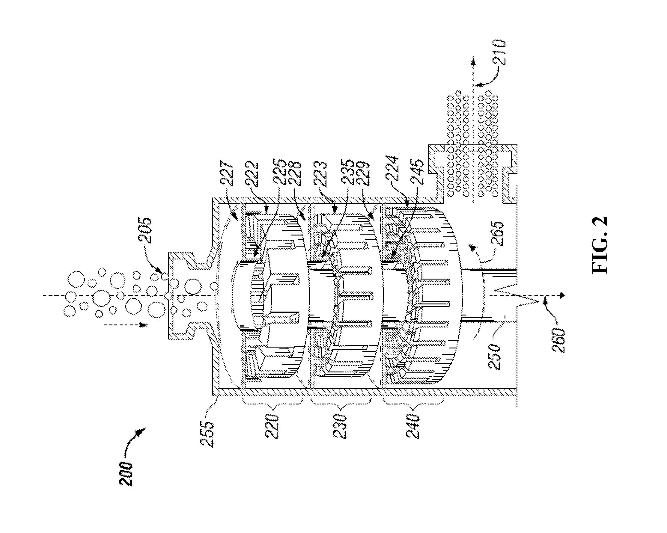
[0032]Overview. Herein disclosed are a system and method for sweetening oil. The oil to be sweetened may be crude oil or an oil derived from crude oil. The system comprises an external high shear mechanical device to provide rapid contact and mixing of reactants in a controlled environment in the reactor / mixer device. Via the disclosed system and method, hydrogen sulfide and sulfur compounds in the oil can be removed as sulfur in dry (or substantially dry) form without producing undesirable emissions. The system and method may be utilized to remove sulfur from oil at the source (e.g., at a wellsite). Desirably, the system is fully modular and / or mobile and utilizable for sweetening sour crude oil proximal the source of the crude. In embodiments, the system is operable as a closed loop.

[0033]In embodiments, the system and method allow desulfurization of oil at substantially atmospheric global operating conditions. Reduction in sulfur content effected by the disclosed system and metho...


PUM

PropertyMeasurementUnit
pressureaaaaaaaaaa
pressureaaaaaaaaaa
tip speedaaaaaaaaaa

Abstract

A method of removing sulfur from sour oil by subjecting sour oil having a first sulfur content to high shear in the presence of at least one desulfurizing agent to produce a high shear treated stream, wherein the at least one desulfurizing agent is selected from the group consisting of bases and inorganic salts, and separating both a sulfur-rich product and a sweetened oil product from the high shear-treated stream, wherein the sulfur-rich product comprises elemental sulfur and wherein the sweetened oil product has a second sulfur content that is less than the first sulfur content. A system for reducing the sulfur content of sour oil via at least one high shear device comprising at least one rotor and at least one complementarily-shaped stator, and at least one separation device configured to separate a sulfur-rich product and sweetened oil from the high shear-treated stream.

Description

CROSS-REFERENCE TO RELATED APPLICATIONS[0001]This application claims the benefit under 35 U.S.C. §119(e) of U.S. Provisional Patent Application No. 61 / 372,013 filed Aug. 9, 2010, the disclosure of which is hereby incorporated herein by reference.STATEMENT REGARDING FEDERALLY SPONSORED RESEARCH OR DEVELOPMENT[0002]Not Applicable.BACKGROUND[0003]1. Technical Field[0004]The present invention relates generally to the removal of sulfur from oil. More particularly, the present invention relates to a system and method for sweetening crude oil. Still more particularly, the present invention relates to a system and method for removal of sulfur from oil via high shear.[0005]2. Background of the Invention[0006]Crude oil is generally associated with significant quantities of hydrogen sulfide and contains various other organic and inorganic sulfur compounds. Natural fossil fuels, such as crude oil and natural gas, that contain a substantial concentration of sulfur compounds, such as hydrogen sul...

Claims


Application Information

Patent Timeline
Patent Type & Authority Applications(United States)
IPC IPC(8): C10G29/00C10G45/02C10G27/12C10G29/02C10G29/20B01F27/93
CPCB01F7/00766B01F13/1016C10G19/02C10G2300/308C10G31/10C10G2300/205C10G2300/202C10G31/09B01F27/2711B01F33/811C10G29/00B01F27/93
Inventor HASSAN, ABBASHASSAN, AZIZANTHONY, RAYFORD G.BORSINGER, GREGORY G.
Owner HRD CORP
Why Eureka
Try Eureka