Ferromagnetic tunnel junction structure and magnetoresistive element using the same

a tunnel junction and magnetoresistive element technology, applied in the field of ferrromagnetic tunnel junction structure and magnetoresistive element using the same, can solve the problems of difficult to obtain large tmr, difficult to obtain high-quality mgo barrier, and inability to obtain high-quality tunnel barrier, so as to achieve coherent tunnelling effect more effectively, good lattice misfit, and large tmr

Inactive Publication Date: 2012-05-10
NAT INST FOR MATERIALS SCI
View PDF3 Cites 20 Cited by
  • Summary
  • Abstract
  • Description
  • Claims
  • Application Information

AI Technical Summary

Benefits of technology

[0027]In the process of studying MTJ elements using various types of Co-based full-Heusler alloy materials, the present inventors have found that in a combination thereof with an MgO barrier, Co2FeAl exhibits an extremely large TMR. Heretofore, Co2FeAl is not a half-metal as mentioned above, and when it has A2, B2 and L21 structures, the spin polarizability thereof is around 0.5, 0.6 and 0.8, respectively; and therefore, it has been considered that a giant TMR could not be expected for the alloy. In fact, the present inventors produced tunnel junction structures using amorphous AlOx barrier and Co2FeAl, and have reported that their maximum TMR is 75% or so at low temperatures and 55% or so at room temperature (Patent Document 1, Non-Patent Document 8). However, an MTJ element using Co2FeAl and MgO barrier was not produced.
[0028]This time the inventors produced tunnel junction structures using Co2FeAl and MgO barrier and, surprisingly have found out a giant TMR over 300% at room temperature, and using it, the inventors have reached the present invention. The reason why such a giant TMR could be obtained is not clear at present, and detailed studied will be needed in future. It may be considered that, among Co-based full-Heusler alloys, Co2FeAl is a material having a larger lattice constant of 0.573 nm, and accordingly, the lattice misfit of the alloy with Cr and MgO is small, and a high-quality epitaxial tunnel junction with good lattice misfit can be obtained at the interface between the buffer layer and the barrier to thereby attain the coherent tunnelling effect more effectively.
[0029]In the invention, the giant TMR can be obtained even when the MgO barrier is formed using a sputtering method not through electron beam vapor deposition. This is a novel discovery no one could heretofore reach using Co-based Heusler alloys. Accordingly, the present tunnel junction structure can be produced even when only a sputtering apparatus is used, and any existing sputtering apparatus can be used for producing the structure, and the invention is applicable to HDD readout heads and MRAM. HDD includes a recording and readout head and a recording medium, and the tunnel junction structure of the invention can be used for readout magnetic heads. MRAM has a structure where tunnel junction structures stacked on MOSFET are arranged like matrices, and the tunnel junction structure of the present invention can be used for the tunnel junction structure therein.
[0030]The tunnel junction structure of the invention including Co2FeAl and MgO barrier can be used in many spintronics devices, for example, spin resonance tunnel elements including a ferromagnetic double-tunnel junction structure that are expected in future, ferromagnetic tunnel elements for use in spin logistic devices such as spin MOSFET or the like for which efficient spin injection into semiconductor is needed, etc. In addition, when a multilayered film of a thin Co2FeAl with a Pt film or a CoPt film or an FePt film is used, then perpendicular magnetization can be realized; and when a ferromagnetic tunnel junction with MgO as a barrier therein is produced using such a multilayered film, then a ferromagnetic tunnel junction structure can be constructed having the ability of perpendicular magnetization and capable of exhibiting a giant TMR. The tunnel junction element of the type can be utilized in gigabit-scale large-capacity MRAM.

Problems solved by technology

In the AlOx barrier, the interface roughness between the ferromagnetic layer and the barrier layer is generally large and the TMR variation is large, and in addition, a large TMR is difficult to be obtained; and therefore, recently, a crystalline MgO barrier has become much used.
However, in MTJ with a full-Heusler alloy, in general, a high-quality MgO barrier is difficult to be obtained; and therefore, an electron beam evaporation method is applied.
However, in case where a Co-based full-Heusler alloy is used as a ferromagnetic layer material, in general, the lattice misfit thereof with MgO is large, and therefore, especially when the MgO barrier is formed using a sputtering method, there occur many dislocations inside the MgO barrier and in the interface between the ferromagnetic layer and the MgO layer, and therefore a high-quality tunnel barrier could not be obtained; and in addition, the Co-based full-Heusler alloy structure on the MgO barrier is often a disordered structure.
Recently, so-called spin-transfer magnetization switching has become important, which is for switching the MTJ magnetization by injection of spin polarization current; and one problem is how to reduce the critical current density necessary for the magnetization switching.
Above all, Co2FeAl has a smallest α (Non-Patent Document 6), and therefore, its use is desired; however, since the alloy is not a half-metal (Non-Patent Document 7), a large TMR is not expected for it.

Method used


Image

  • Ferromagnetic tunnel junction structure and magnetoresistive element using the same
  • Ferromagnetic tunnel junction structure and magnetoresistive element using the same
  • Ferromagnetic tunnel junction structure and magnetoresistive element using the same

Examples


example 1

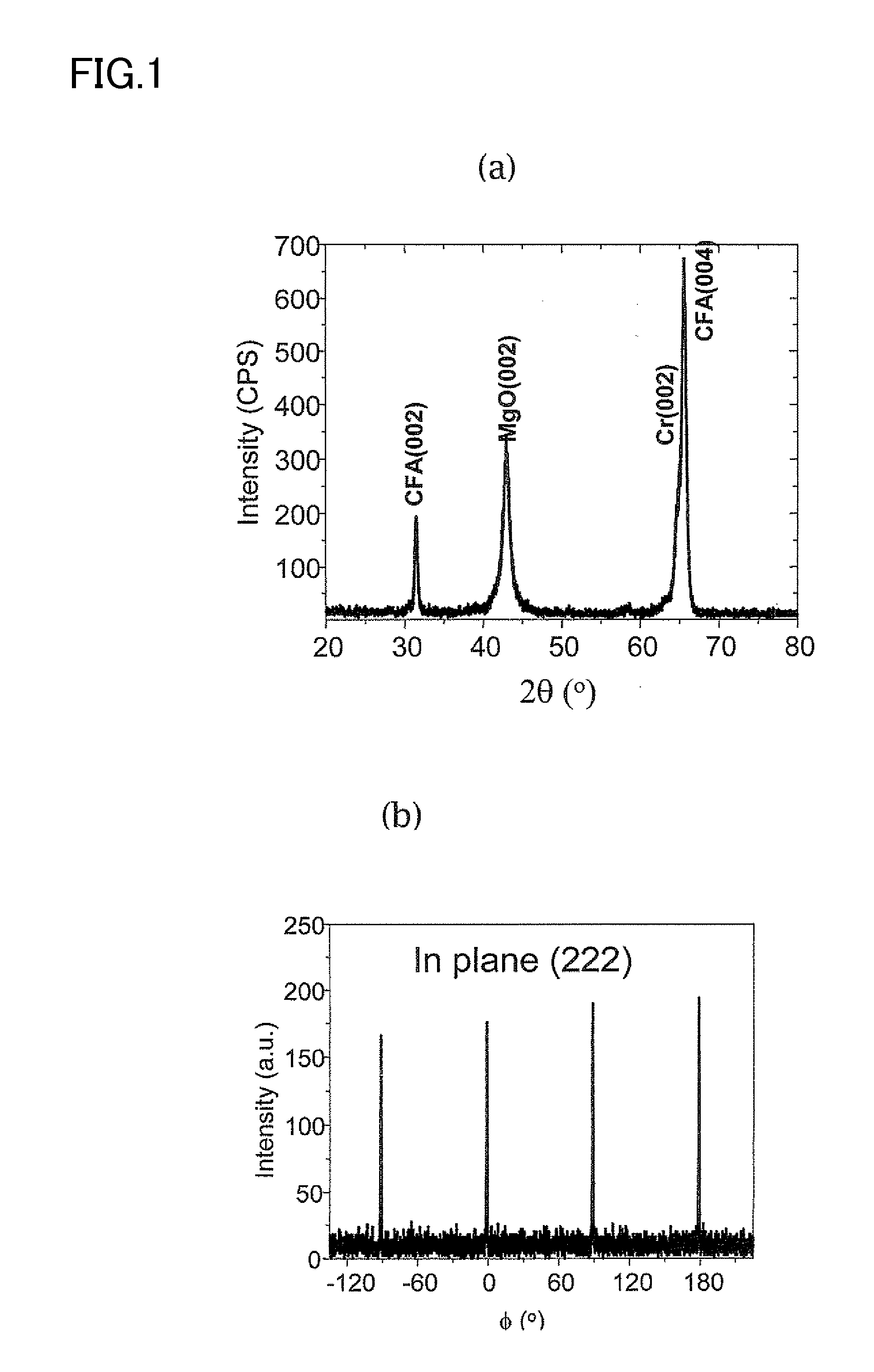
[0047]Using a magnetron sputtering apparatus, a Cr(40) / Co2FeAl(30) stacked film was formed on an MgO (001) substrate, using a Cr film as the buffer layer therein. The parenthesized numerical value means the film thickness of the layer (unit, nm); and the same shall apply hereinunder. Afterwards, for bettering the crystalline property of the Co2FeAl (CFA) film, the film was heat-treated at a temperature of 480° C. for 1 hour. X-ray diffraction thereof revealed that CFA in that condition had a B2 structure. Subsequently, an MgO target was sputtered to form an MgO barrier having a thickness of 1.8 nm. Further subsequently, a CoFe(2) / IrMn(12) / Ru(7) stacked film was formed at room temperature, thereby producing a spin-valve type tunnel junction structure. IrMn is an antiferromagnetic material, and has a role of pinning the spin of the upper CoFe ferromagnetic layer. Ru is a protective film and serves as a mask in microfabrication.

[0048]Afterwards, the stacked film was microfabricated to ...

example 2

[0054]A ferromagnetic tunnel junction structure of MgO(001) substrate / MgO(10) / CFA(30) / MgO(2) / CoFe(2) / IrMn(10) / Ru(7) was produced according to the same method as in Example 1, except that an MgO buffer was used in place of the Cr buffer, and was evaluated in point of the TMR characteristics thereof. As a result, a highest TMR of 150% at room temperature was obtained, though smaller than that in the case of using the Cr buffer layer.

example 3

[0055]A ferromagnetic tunnel junction structure of Cr(40) / CFA(30) / MgO(1.8) / CFA(5) / CoFe(3) / IrMn(12) / Ru(7) was produced according to the same method as in Example 1, in which CFA was used for both the lower and upper magnetic layers. In this case, Ta =400° C. As a result of measurement of TMR, a large TMR of 188% at room temperature and 310% at 10K was obtained. The reason why TMR herein is smaller than that in Example 1 is not clear at present; however, the reason may be because the degree of (100) orientation of the upper CFA on the MgO barrier is not sufficient like that in Example 1, and the interfacial structure between the upper CFA and MgO is not ideal, and therefore it may be considered that the contribution of the coherent tunnel effect could not be on the same level as that in Example 1. In fact, as shown in FIG. 7, the bias dependence of differential conductance dl / dV showed the minimum only on one side (negative side), and obviously different from FIG. 4, a coherent tunnel...


PUM


Abstract

For the present ferromagnetic tunnel junction structure, employed is a means characterized by using an MgO barrier and using a Co2FeAl full-Heusler alloy for any of the ferromagnetic layers therein. The ferromagnetic tunnel junction structure is characterized in that Co2FeAl includes especially a B2 structure and one of the ferromagnetic layers is formed on a Cr buffer layer. The magnetoresistive element is characterized in that the ferromagnetic tunnel junction structure therein is any of the above-mentioned ferromagnetic tunnel junction structure. Accordingly, a large TMR, especially a TMR over 100% at room temperature can be attained, using Co2FeAl having a smallest α though not a half-metal.

Description

TECHNICAL FIELD[0001]The present invention relates to a ferromagnetic tunnel junction structure comprising a tunnel barrier layer disposed between two ferromagnetic layers, in particular to a spin-valve ferromagnetic tunnel junction structure in which the magnetization of one of the ferromagnetic layers is pinned by an antiferromagnetic layer and to a magnetoresistive element using the same.BACKGROUND ART[0002]In recent years, a Giant Magnetoresistance (GMR) effect element comprising a multilayer film of a ferromagnetic layer / non-magnetic metal layer and a ferromagnetic tunnel junction (MTJ) comprising a ferromagnetic layer / insulator layer / ferromagnetic layer have attracted attention for new magnetic field sensors and non-volatile magnetic random access memory (MRAM) cells. With respect to the GMR, there have been known a CIP-GMR of a type such that an electric current flows within the plane of the film and a CPP-GMR of a type such that an electric current flows in the direction per...

Claims


Application Information

Patent Timeline
Patent Type & Authority Applications(United States)
IPC IPC(8): H01L29/82H01L21/02
CPCB82Y10/00B82Y25/00G01R33/098G11B5/3906H01L43/10G11B2005/3996H01F10/3254H01L43/08G11B5/3909H01F10/1936H10N50/10H10N50/85
Inventor INOMATA, KOICHIROWANG, WENHONGSUKEGAWA, HIROAKI
Owner NAT INST FOR MATERIALS SCI
Why Eureka
Try Eureka