Ferromagnetic tunnel junction structure and magnetoresistive element using the same
a tunnel junction and magnetoresistive element technology, applied in the field of ferrromagnetic tunnel junction structure and magnetoresistive element using the same, can solve the problems of difficult to obtain large tmr, difficult to obtain high-quality mgo barrier, and inability to obtain high-quality tunnel barrier, so as to achieve coherent tunnelling effect more effectively, good lattice misfit, and large tmr
- Summary
- Abstract
- Description
- Claims
- Application Information
AI Technical Summary
Benefits of technology
Problems solved by technology
Method used
Image
Examples
example 1
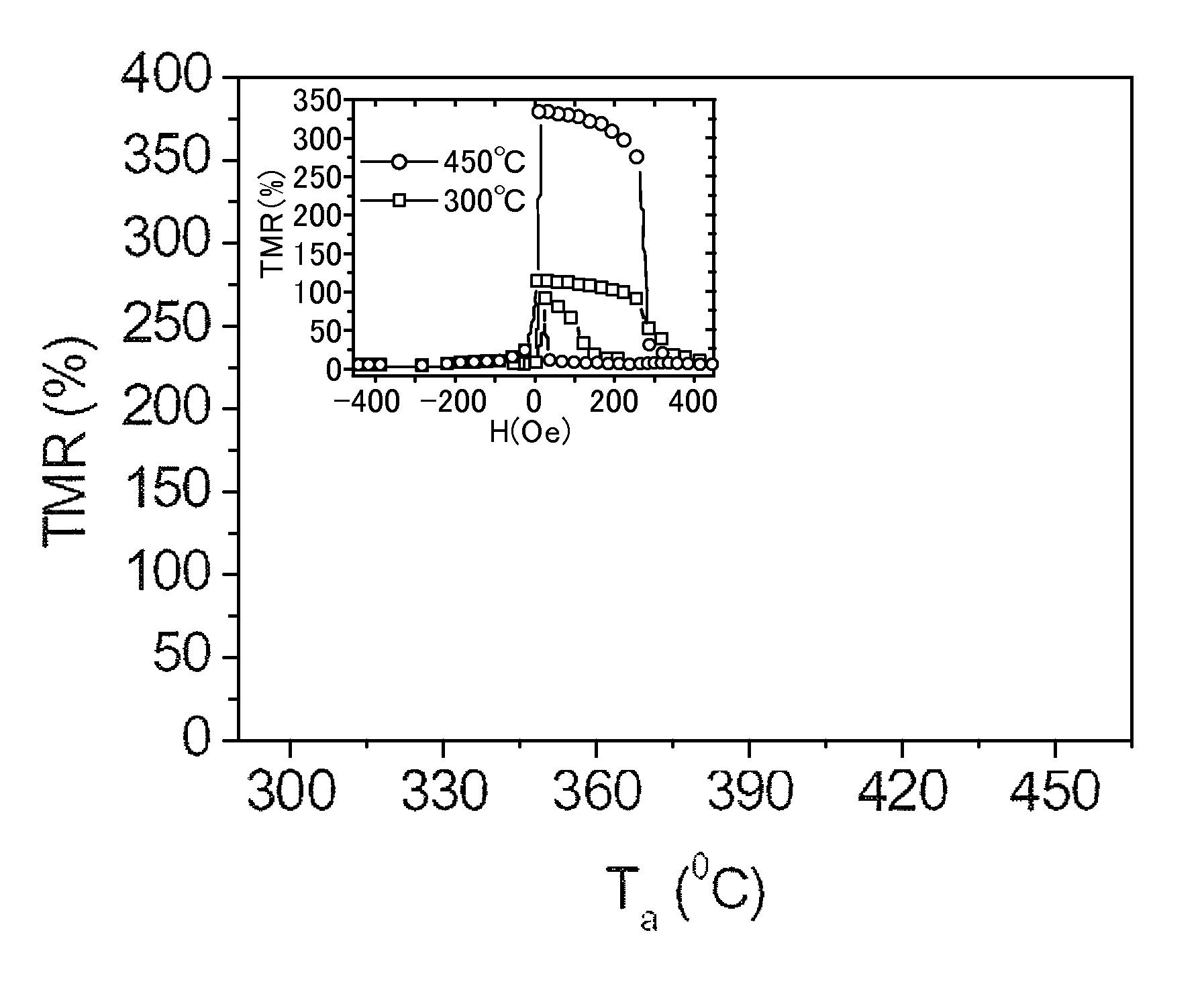
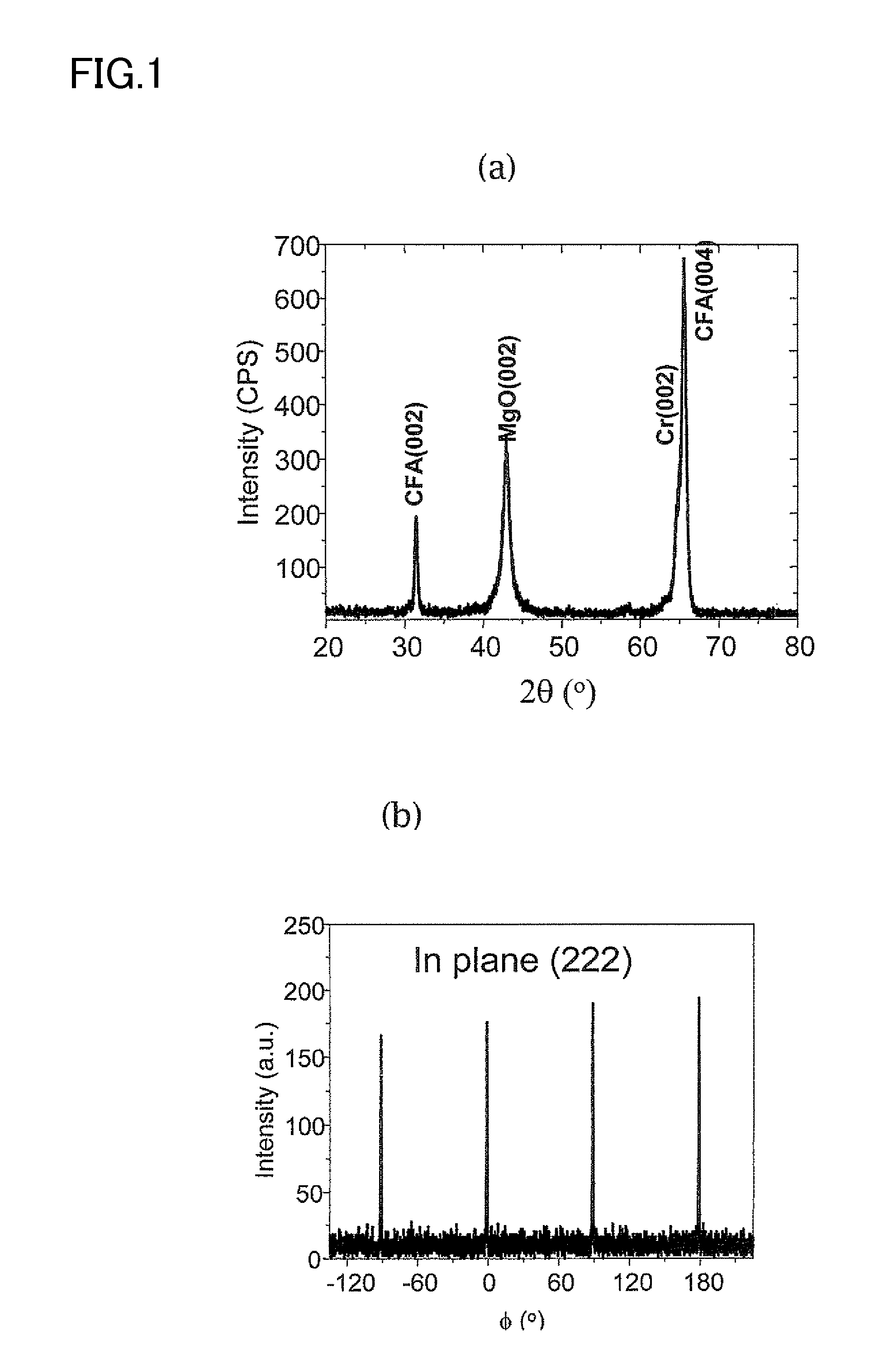
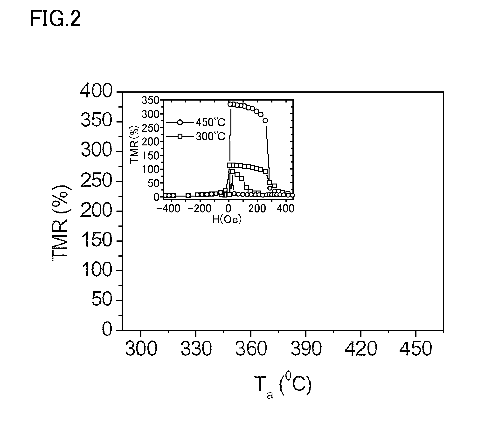
[0047]Using a magnetron sputtering apparatus, a Cr(40) / Co2FeAl(30) stacked film was formed on an MgO (001) substrate, using a Cr film as the buffer layer therein. The parenthesized numerical value means the film thickness of the layer (unit, nm); and the same shall apply hereinunder. Afterwards, for bettering the crystalline property of the Co2FeAl (CFA) film, the film was heat-treated at a temperature of 480° C. for 1 hour. X-ray diffraction thereof revealed that CFA in that condition had a B2 structure. Subsequently, an MgO target was sputtered to form an MgO barrier having a thickness of 1.8 nm. Further subsequently, a CoFe(2) / IrMn(12) / Ru(7) stacked film was formed at room temperature, thereby producing a spin-valve type tunnel junction structure. IrMn is an antiferromagnetic material, and has a role of pinning the spin of the upper CoFe ferromagnetic layer. Ru is a protective film and serves as a mask in microfabrication.
[0048]Afterwards, the stacked film was microfabricated to ...
example 2
[0055]A ferromagnetic tunnel junction structure of MgO(001) substrate / MgO(10) / CFA(30) / MgO(2) / CoFe(2) / IrMn(10) / Ru(7) was produced according to the same method as in Example 1, except that an MgO buffer was used in place of the Cr buffer, and was evaluated in point of the TMR characteristics thereof. As a result, a highest TMR of 150% at room temperature was obtained, though smaller than that in the case of using the Cr buffer layer.
example 3
[0056]A ferromagnetic tunnel junction structure of Cr(40) / CFA(30) / MgO(1.8) / CFA(5) / CoFe(3) / IrMn(12) / Ru(7) was produced according to the same method as in Example 1, in which CFA was used for both the lower and upper magnetic layers. In this case, Ta =400° C. As a result of measurement of TMR, a large TMR of 188% at room temperature and 310% at 10K was obtained. The reason why TMR herein is smaller than that in Example 1 is not clear at present; however, the reason may be because the degree of (100) orientation of the upper CFA on the MgO barrier is not sufficient like that in Example 1, and the interfacial structure between the upper CFA and MgO is not ideal, and therefore it may be considered that the contribution of the coherent tunnel effect could not be on the same level as that in Example 1. In fact, as shown in FIG. 7, the bias dependence of differential conductance dl / dV showed the minimum only on one side (negative side), and obviously different from FIG. 4, a coherent tunnel...
PUM
| Property | Measurement | Unit |
|---|---|---|
| temperature | aaaaa | aaaaa |
| temperature | aaaaa | aaaaa |
| temperature | aaaaa | aaaaa |
Abstract
Description
Claims
Application Information
 - R&D
- Intellectual Property
- Life Sciences
- Materials
- Tech Scout
- Unparalleled Data Quality
- Higher Quality Content
- 60% Fewer Hallucinations
Browse by: Latest US Patents, China's latest patents, Technical Efficacy Thesaurus, Application Domain, Technology Topic, Popular Technical Reports.
© 2025 PatSnap. All rights reserved.Legal|Privacy policy|Modern Slavery Act Transparency Statement|Sitemap|About US| Contact US: help@patsnap.com


