Magnetic tunnel junction, magnetoresistive element and spintronics device in which said magnetic tunnel junction is used, and method of manufacturing magnetic tunnel junction

a technology of magnetoresistive elements and magnetic tunnel junctions, which is applied in the field of magnetic tunnel junctions, magnetoresistive elements and spintronics devices in which the magnetic tunnel junction is used, and the method of manufacturing magnetic tunnel junctions, can solve the problems of difficult to draw tmr characteristics, difficult to change, and limited ferromagnetic layer materials, etc., to achieve efficient manufacturing of mtj elements, high tmr ratio, and large tmr ratio

Active Publication Date: 2021-04-29
NAT INST FOR MATERIALS SCI
View PDF0 Cites 3 Cited by
  • Summary
  • Abstract
  • Description
  • Claims
  • Application Information

AI Technical Summary

Benefits of technology

[0030]According to the MTJ element of the present invention, by using the MTJ element that combines a crystalline barrier layer made of a cubic nonmagnetic material having a spinel structure and a Co-based Heusler alloy layer having high polarization, a high TMR ratio can be exhibited at a room temperature and a lattice-matched interface can be obtained, whereby a large TMR ratio at a room temperature can be utilized even at a high applied voltage.
[0031]According to the method of manufacturing a magnetic tunnel junction of the present invention, it is possible to...

Problems solved by technology

However, it is not easy for changing the characteristics of the MgO barrier including its lattice constant and bandgap, whereby the ferromagnetic layer material has a problem of being limited strictly.
Since the MgO has lattice mismatch of, for example, 3% to 4% with CoFe-based alloys, 3% to 6% with Co-based Heusler alloys that are known as high spin-polarized materials and about 10% with FePt, misfit dislocation is inevitably and densely introduced to these interfaces due to the lattice mismatch, so that it is difficult to draw the TMR characteristics.
However, it is known that, in the case of adopting the MgAl2O4 barrier, there is a critical problem that the TMR enhancement effect due to the coherent tunnel effect is small, and t...

Method used


Image

  • Magnetic tunnel junction, magnetoresistive element and spintronics device in which said magnetic tunnel junction is used, and method of manufacturing magnetic tunnel junction
  • Magnetic tunnel junction, magnetoresistive element and spintronics device in which said magnetic tunnel junction is used, and method of manufacturing magnetic tunnel junction
  • Magnetic tunnel junction, magnetoresistive element and spintronics device in which said magnetic tunnel junction is used, and method of manufacturing magnetic tunnel junction

Examples


example 1

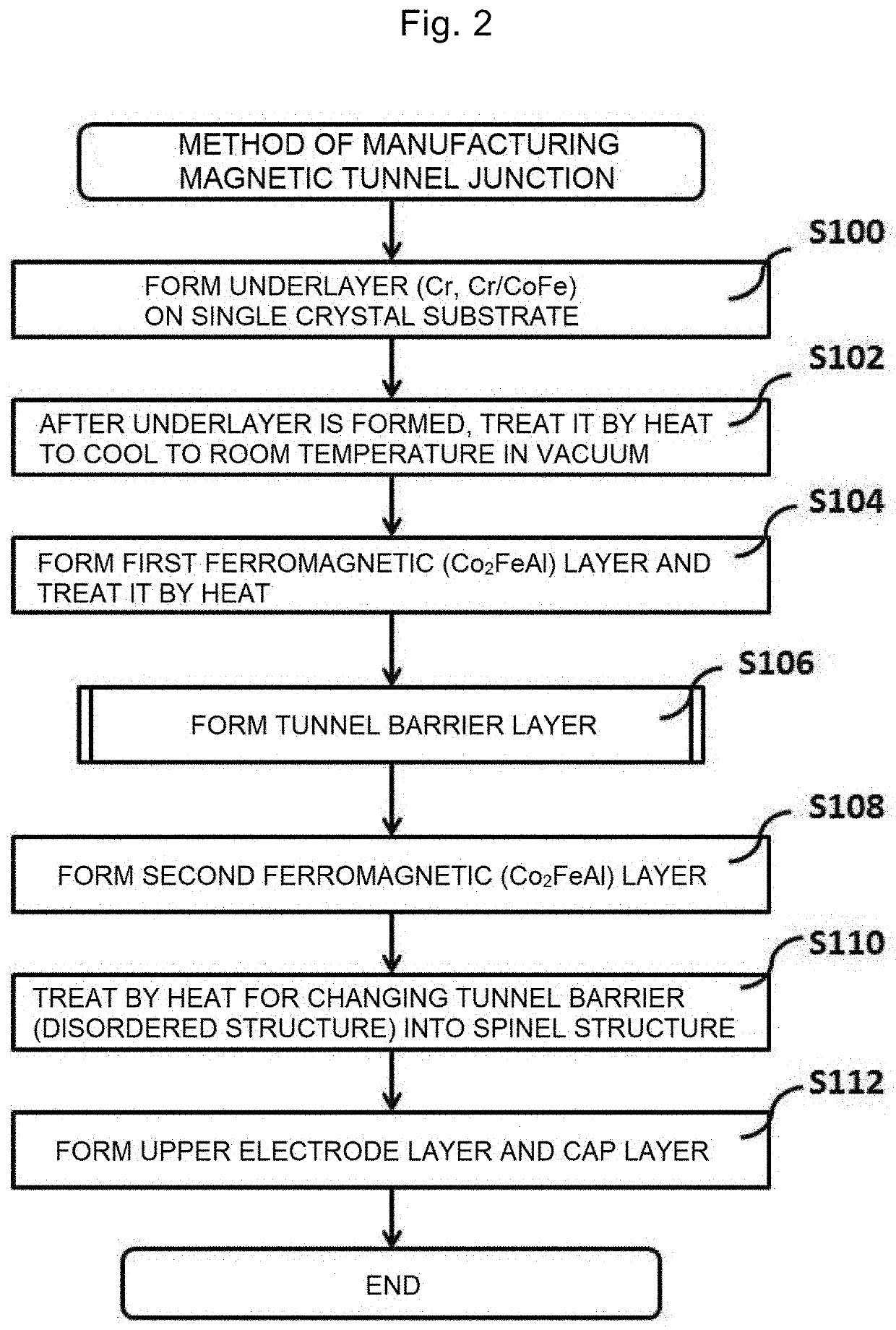
[0064]Firstly, a method of manufacturing a Co-based Heusler alloy layer, which is the second ferromagnetic layer 6, adjacently on a spinel MgAl2O4 layer, which is the barrier layer 5, will be shown with reference to FIG. 4. As an example of the Co-based Heusler alloy layer, a case of a Co2FeAl layer will be described. Using an ultrahigh vacuum direct current magnetron sputtering apparatus, a Cr layer (40 nm) was manufactured as an underlayer on a single crystal MgO (001) substrate at a room temperature. For improving crystallinity and flatness, the Cr layer was treated by heat at 500° C. in a vacuum chamber for 1 hour after it was formed, and then was cooled to a room temperature. Thereon, a CoFe layer (10 nm) was manufactured from a Co50Fe50 composition target by sputtering, was subsequently treated by heat at 250° C. in a vacuum chamber for 15 minutes, and was cooled to a room temperature.

[0065]Subsequently, Mg (0.45 nm) was formed at a room temperature, and this laminated film wa...

example 2

[0070]Next, an example of forming an MTJ element by applying the method shown in Example 1 will be described with reference to FIG. 5.

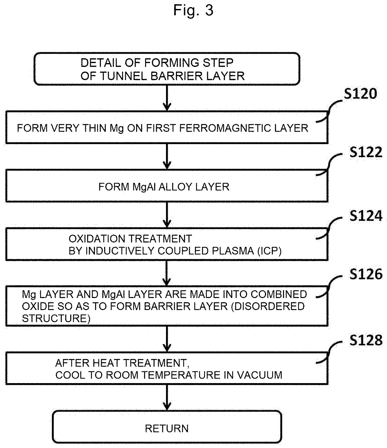
[0071]Using the same ultrahigh vacuum direct current magnetron sputtering apparatus as that in Example 1, a film having two layers of Cr (40 nm) / CoFe (5 nm) was manufactured as an underlayer on a single crystal MgO (001) substrate at a room temperature. After the formation of the Cr layer, heat treatment was carried out at 500° C. in vacuum. Thereon, Co2FeAl (5 nm) was manufactured as the first ferromagnetic layer by sputtering in the same method as that in Example 1. Thereafter, the Co2FeAl film was treated by heat at 250° C. similarly to the underlayer in order to improve the crystallinity of the Co2FeAl film, and was cooled to a room temperature. Subsequently, Mg (0.45 nm) was formed at a room temperature, and this laminated film was moved into a chamber for oxidation. Subsequently, a layer of Mg (0.45 nm) / MgAl alloy (0.75 nm) was formed in the sam...

example 3

[0075]Next, an example of forming an MTJ element by applying the method described in Example 2 so as to improve a TMR ratio will be described with reference to FIGS. 6 to 9. Using the same apparatus and method as those in Example 2, a multilayer film of Cr (40 nm) / CoFe (5 nm) / lower Co2FeAl (5 nm) was formed on an MgO (001) substrate. Thereafter, a CoFe layer of 0.5 nm was formed by a direct current sputtering method. Immediately thereafter, the film was treated by heat at 250° C. in vacuum for 15 minutes, and was cooled to a room temperature. Subsequently, an MgAl2O4 barrier layer and an upper Co2FeAl layer were formed by the same method as those in Examples 1 and 2, and were treated by heat at a temperature of TCFA=550° C. in vacuum. After cooling to a room temperature, a laminated film of CoFe (0.5 nm) / IrMn (12 nm) / Ru (10 nm) was formed as an upper electrode layer by the same method as that in Example 2, thereby manufacturing a spin valve-type MTJ element. Then, after carrying out...


PUM


Abstract

The object of the present invention is to attain an unconventionally high tunnel magnetoresistance (TMR) ratio by using a barrier layer made of an MgAl2O4 type insulator material with a spinel structure. The problem can be solved by a magnetic tunnel junction in which a barrier layer is made of a cubic nonmagnetic material having a spinel structure, and both of two ferromagnetic layers that are adjacently on and below the barrier layer are made of a Co2FeAl Heusler alloy. Preferably, the nonmagnetic material is made of oxide of an Mg1-31 xAlx (0<x≤1) alloy, and exhibits tunnel magnetoresistance of 250% or more and 34000% or less at a room temperature.

Description

TECHNICAL FIELD[0001]The present invention relates to a magnetic tunnel junction having a structure in which a tunnel barrier layer is sandwiched by two ferromagnetic layers, and relates to its application to a magnetoresistive element and a spintronics device which use the same.[0002]Further, the present invention relates to a method of manufacturing a magnetic tunnel junction having the structure in which the tunnel barrier layer is sandwiched by two ferromagnetic layers.BACKGROUND ART[0003]A magnetic tunnel junction (MTJ element) including trilayers of a ferromagnetic layer / an insulator tunnel barrier layer (barrier layer) / a ferromagnetic layer has been practically used as a magnetic head for a hard disk and a nonvolatile magnetic random access memory (MRAM) so far. In an MRAM, MTJ elements are arranged in a two-dimensional matrix, and two magnetic layers that constitute each MTJ element are controlled to be parallel and antiparallel with each other in a current direction by usin...

Claims


Application Information

Patent Timeline
IPC IPC(8): G01R33/09H01L43/08H01L43/10H01L43/12H01L43/02G11C11/16G11B5/39
CPCG01R33/098G01R33/093H01L43/08G11B5/3909H01L43/12H01L43/02G11C11/161H01L43/10G01R33/09G11B5/39H01F41/18H01L29/82H10N50/01H10N50/85H10N50/10H10N50/80
Inventor SUKEGAWA, HIROAKISCHEIKE, THOMASMITANI, SEIJIOHKUBO, TADAKATSUHONO, KAZUHIROINOMATA, KOUICHIRO
Owner NAT INST FOR MATERIALS SCI
Why Eureka
Try Eureka