Composite seed structure to improve pma for perpendicular magnetic pinning

a perpendicular magnetic pinning and composite seed technology, applied in the direction of magnetic bodies, spin-exchange-coupled multilayers, substrate/intermediate layers, etc., can solve the problems of making both device design and patterning process difficult for high density memory applications, and achieve enhanced pma, good crystalline transition, and strong anti-ferromagnetic coupling

Active Publication Date: 2022-02-24
GUO YIMIN +2
View PDF0 Cites 0 Cited by
  • Summary
  • Abstract
  • Description
  • Claims
  • Application Information

AI Technical Summary

Benefits of technology

[0011]The present invention further discloses an alloy AFC spacer (AAS). The AAS is a metal alloy comprising at least one of the following elements Ru, Rh, Cr, Ir or an alloy thereof and at least one of the following elements Mo, W, Nb, Cr or an alloy thereof. Since a perpendicular magnetic reference layer (pMRL) is a body-center-cubic (BCC) crystalline structure for a high TMR ratio, the alloy AFC spacer (AAS) serves for a good crystalline transition and a strong anti-ferromagnetic coupling between the CSS / pMPL and pMRL. A sequential deposition of above four layers constitutes a strong perpendicular magnetic pinning element (pMPE): CSS / pMPL / AAS / pMRL with an enhanced PMA, an anti-ferromagnetic coupling (AFC) as well as a desired crystalline structure arrangement for a high TMR ratio.

Problems solved by technology

This pMTJ comprises a thick pMPE film stack having a large magnetic moment which makes both device design and patterning process difficult for high density memory applications.

Method used


Image

  • Composite seed structure to improve pma for perpendicular magnetic pinning
  • Composite seed structure to improve pma for perpendicular magnetic pinning
  • Composite seed structure to improve pma for perpendicular magnetic pinning

Examples


first embodiment

of a Full pSTT-MTJ Film

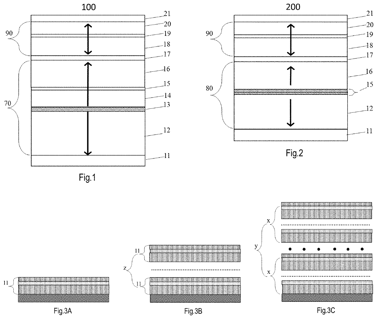
[0032]FIG. 4 is a bottom-pinned pSTT-MTJ film (300) with a thick SAF stack. Its layer-by-layer structure sequentially from bottom to top is as follows: a base-layer (10) was first grown on a device substrate (not shown here); followed by a composite seed structure (CSS) (11) comprising ML(11-1) / BL(11-2) / TL(11-3); followed by a thick SAF stack (12 / 13 / 14) of [Co / Pt or Pd]nCo / Ru / Co / [(Pt or Pd) / Co]m in which the thickness of Co is between 0.3 nm and 0.7 nm, the thickness of Pt (or Pd) is between 0.2 nm and 0.8 nm, and the repetition numbers (m>n) are between 2 and 6 for n and between 1 and 4 for m; followed by a crystalline structure transition layer (15) of Ta, W, or Mo with a thickness between 0.1 nm and 0.5 nm; and a magnetic reference layer (16) of CoFeB with a thickness between 0.9 nm and 1.3 nm; a tunnel barrier (17) of MgO between 0.8 nm and 1.2 nm, a magnetic free layer; and a capping stack (21) of MgO(1.0-1.5 nm) / W(1-3 nm) / R (2-5 nm). The magnetic free la...

second embodiment

of a Full pSTT-MTJ Film

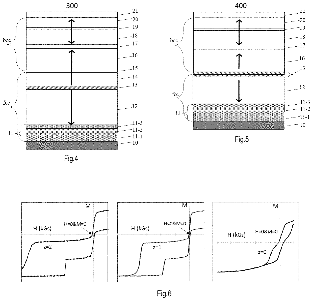
[0033]FIG. 5 is a bottom-pinned pSTT-MTJ film (400) with a thin tSAF stack. Its layer-by-layer structure sequentially from bottom to top is: a base-layer (10) was first grown on a device substrate (not shown here); followed by a composite seed structure (CSS) (11) comprising ML(11-1) / BL(11-2) / TL(11-3); followed by a magnetic super-lattice multilayer (12) of [Co / X]n / Co (n is an integer between 2 and 6) in which each Co layer has a thickness between 0.25 and 0.6 nm and each of X is one of Pt, Pd or Ni and has a thickness between 0.2 and 0.4 nm; an alloy AFC layer (13) of RuMo, RhMo, RuW, RhW or CrMo; a reference layer of FeB, FeB / CoFeB or CoFeB; a tunnel barrier MgO (17); a tri-layer recording layer having a first magnetic material layer (18), a non-magnetic Boron absorbing layer (19) of Mo, W or Ta, and a second magnetic material layer (20); a capping layer (21) of MgO / W, MgOFe / W, MgO / Fe / W, MgZnO / W or MgO / W / Ru. In the above stack, the thickness of RuMo, RhMo Ru...

third embodiment

of a Full pSTT-MTJ Film

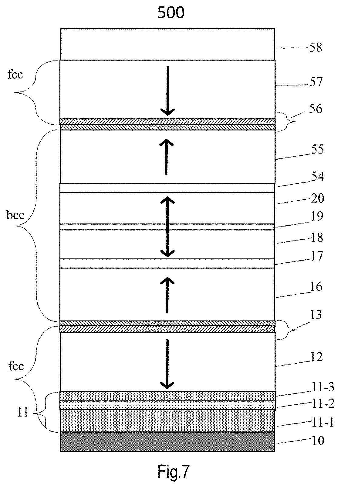
[0035]FIG. 7 is a dual-pinned pSTT-MRAM (500) with a thin tSAF and a CSS at bottom. A typical structure of stack 500 including base-layer (10) / CSS(11) / [Co / (Pt, Pd or Ni)]n / Co(12) / (Ru / Cr)(13) / Fe / CoFeB (16) / MgO(17) / CoFeB (18) / (W or Mo)(19) / CoFeB (20) / MgO(54) / CoFeB / (55) / Fe / (Cr / (Ru)(56) / Co / [(Pt, Pd or Ni) / Co]n(57) / cap layer (58). During high temperature annealing, said CSS (11) will force the two multi-layers [Co / (Pt, Pd or Ni)]n in contact with from the bottom (12,13) layers and top (56,57) layer to transform into FCC crystalline structure with (111) orientation aligned normal to the film surface and all the middle (16,17,18,19,20,54,55) layers to transform into BCC crystalline structure with (100) orientation, which not only allows to further increase the perpendicular anisotropy (PMA) to the free layer (FL) and thus increase the thermal stability and prolong the retention time of MRAM device, but also allows to increase the thickness of the FL (from 1.8 nm for ...


PUM

PropertyMeasurementUnit
crystalline lattice constantaaaaaaaaaa
thicknessaaaaaaaaaa

Abstract

The invention comprises a novel composite seed structure (CSS) having lattice constant matched crystalline structure with the Co layer in above perpendicular magnetic pinning layer (pMPL) so that an excellent epitaxial growth of magnetic super lattice pinning layer [Co/(Pt, Pd or Ni)]n along its FCC (111) orientation can be achieved, resulting in a significant enhancement of perpendicular magnetic anisotropy (PMA) for perpendicular spin-transfer-torque magnetic-random-access memory (pSTT-MRAM) using perpendicular magnetoresistive elements as basic memory cells which potentially replace the conventional semiconductor memory used in electronic chips, especially mobile chips for power saving and non-volatility.

Description

CROSS-REFERENCE TO RELATED APPLICATIONS[0001]This application is a continuation-in-part of and claims the benefit of co-pending U.S. patent application Ser. No. 16 / 786,304, filed Feb. 10, 2020, entitled A NOVEL LATTICE MATCHED SEED LAYER TO IMPROVE PMA FOR PERPENDICULAR MAGNETIC PINNING.BACKGROUND OF THE INVENTION1. Field of the Invention[0002]This invention relates to a novel composite seed structure (CSS) to improve perpendicular magnetic anisotropy (PMA) for magnetic pinning multilayer in a magnetic structure, such as a perpendicular magnetic tunnel junction (pMTJ). It can in particular be used in magnetic memory, magnetic logic, spin-torque oscillator and magnetic sensor applications.2. Description of the Related Art[0003]In recent years, magnetic random access memories (hereinafter referred to as MRAMs) using the magnetoresistive effect of ferromagnetic tunnel junctions (also called MTJs) have been drawing increasing attention as the next-generation solid-state nonvolatile memo...

Claims


Application Information

Patent Timeline
Patent Type & Authority Applications(United States)
IPC IPC(8): H01F10/32H01L43/02H01L43/12H01F41/32
CPCH01F10/3286H01L43/02H01L43/12H01L43/10H01F10/3254H01F10/3272H01F10/329H01F41/32H01F10/30H01F41/307H01F10/3236H10N50/10H10N50/85H10N50/01H10N50/80
Inventor GUO, YIMINXIAO, RONGFUCHEN, JUN
Owner GUO YIMIN
Why Eureka
Try Eureka