MTJ incorporating CoFe/Ni multilayer film with perpendicular magnetic anisotropy for MRAM application

a multi-layer film, perpendicular magnetic anisotropy technology, applied in the direction of magnetic bodies, instruments, record information storage, etc., can solve the problems of too high low switching, too high external magnetic fields generated by current carrying lines to switch the magnetic moment direction, etc., to minimize the impinging ion energy, low rf power, and high inert gas pressure

Active Publication Date: 2012-05-22
TAIWAN SEMICON MFG CO LTD
View PDF29 Cites 48 Cited by
  • Summary
  • Abstract
  • Description
  • Claims
  • Application Information

AI Technical Summary

Benefits of technology

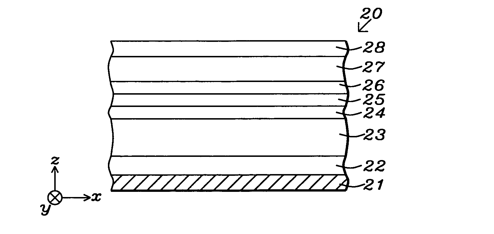
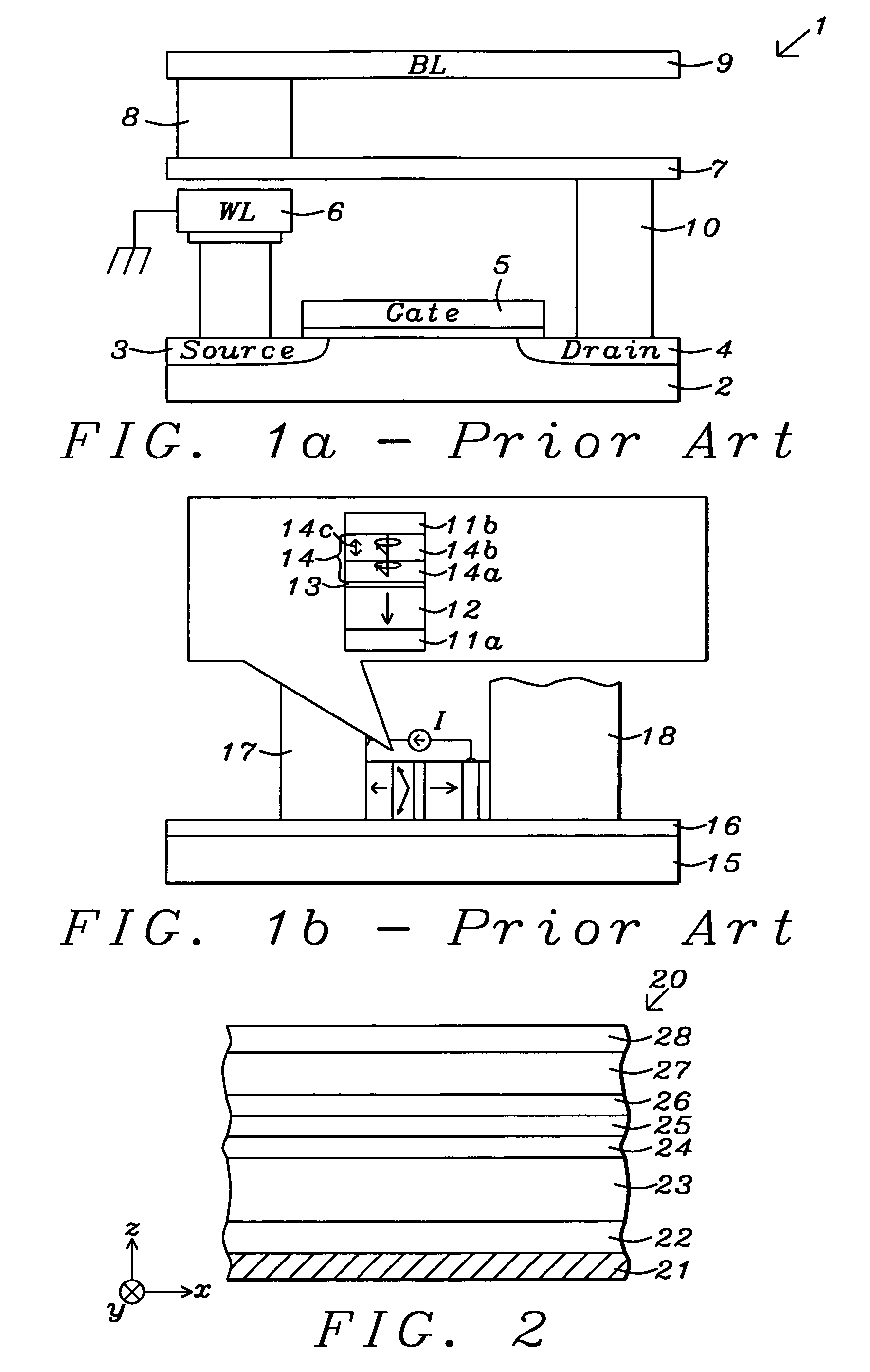
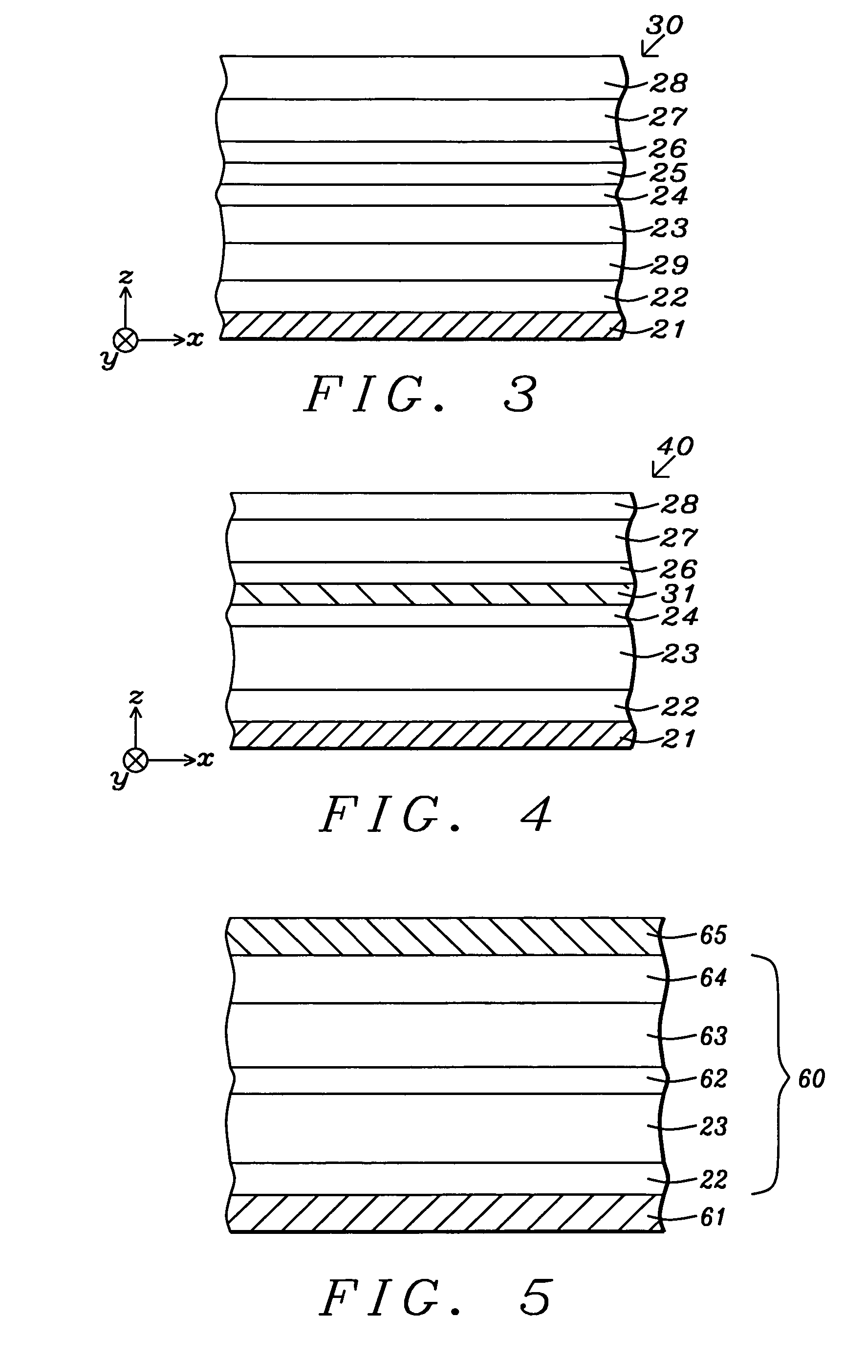
[0015]One objective of the present invention is to provide one or more MTJ layers with high perpendicular magnetic anisotropy, high Mst (magnetic saturation x thickness), and high spin polarization for advanced MRAM structures including spintronic and MAMR devices, and a thin seed layer for enhancing the PMA in the aforementioned layers.
[0016]A second objective of the present invention is to provide a MTJ incorporating one or more layers with high PMA and a thin seed layer according to the first objective that also has improved thermal stability for high density MRAM.
[0022]An important feature of all embodiments is that each of the layers in the CoFe / Ni, CoFeR / Ni, Co / NiFe, Co / NiCo, CoFe / NiFe, and CoFe / NiCo laminated structures is deposited with a very low RF power and a high inert gas pressure to minimize the impinging ion energy so that deposition of a layer does not damage a previously deposited layer. Thus, the interfaces between adjoining layers are preserved to maximize the PMA property. Furthermore, this method enables the PMA of the laminated structures to be preserved with a substantially thinner seed layer.

Problems solved by technology

As the size of MRAM cells decreases, the use of external magnetic fields generated by current carrying lines to switch the magnetic moment direction becomes problematic.
As a result, spin valve structures based on PMA are capable of scaling for higher packing density which is one of the key challenges for future MRAM applications and other spintronic devices.
09). However, in the GMR devices described in the prior art, typical switching current density is above 10 milli-amp / cm2 which is too high for low switching current
MRAM. Furthermore, the MR ratio is around 1% which is too small for the readout signal in
Unfortunately, high temperatures are not so practical for device integration.
However, none of the aforementioned references discuss a laminated free layer or reference layer with perpendicular magnetic anisotropy.

Method used


Image

  • MTJ incorporating CoFe/Ni multilayer film with perpendicular magnetic anisotropy for MRAM application
  • MTJ incorporating CoFe/Ni multilayer film with perpendicular magnetic anisotropy for MRAM application
  • MTJ incorporating CoFe/Ni multilayer film with perpendicular magnetic anisotropy for MRAM application

Examples


example 1

[0062]An experiment was performed to demonstrate the magnitude of perpendicular magnetic anisotropy in laminated layers formed according to an embodiment of the present invention. A partial spin valve stack comprised of a composite Ta10 / Ru20 / Cu30 seed layer, a (CoFe / Ni)x laminated layer where each CoFe layer is 2 Angstroms thick and each Ni layer is 6 Angstroms thick, and a Ru10 / Ta40 / Ru30 cap layer was fabricated in order to obtain PMA values from MH curves using a vibrating sample magnometer (VSM). The thickness of each layer in the composite seed layer and in the composite cap layer is shown by the number following each of the elements. The results are illustrated in FIGS. 8-12 and indicate a substantial PMA can be achieved in several examples of (CoFe / Ni)x laminates involving a variety of CoFe alloys such as Co90Fe10 (FIG. 9), Co75Fe25(FIG. 10), Co50Fe50(FIG. 11), and Co30Fe70 (FIG. 12). The (Co / Ni)20 example (FIG. 8) was previously reported in related patent application Ser. No....

example 2

[0063]In a second experiment, a MTJ with a CPP-TMR configuration according to the first embodiment was fabricated to demonstrate the effectiveness of laminated (CoFe / Ni)x reference and free layers in providing high PMA. The resulting MTJ structure is represented by Ta10 / Ru20 / Cu30 / (Co(100-Z)FeZ2 / Ni5)x / CoFeB10 / Co(100-Z)FeZ2-8 / MgO / Co(100-Z)FeZ2-8 / CoFeB10 / (Co(100-Z)FeZ2 / Ni5)Y / Ru10 / Ta40 / Ru30 where x, y, and z are values described previously and the number following each material is its thickness. The MTJ full film (unpatterned) stack of layers was found to have a TMR ratio, Hk, and other magnetic properties acceptable for use in high performance MRAM or STT-RAM structures. Hc is about 1000 Oe for this MTJ structure.

example 3

[0064]In another experiment, a MTJ full film stack with a CPP-TMR configuration was fabricated according to the second embodiment of the present invention. The resulting MTJ has a similar configuration to that in Example 2 except the upper Cu layer in the composite seed layer is replaced by an IrMn AFM layer and is represented by the following: Ta10 / Ru20 / IrMn70 / (Co(100-Z)FeZ2 / Ni5)x / CoFeB10 / Co(100-Z)FeZ2-8 / MgO / Co(100-Z)FeZ2-8 / CoFeB10 / (Co(100-Z)FeZ2 / Ni5)Y / Ru10 / Ta40 / Ru30. Again, Hk>15000 Oe and Hc is approximately 1000 Oe.


PUM

PropertyMeasurementUnit
thicknessaaaaaaaaaa
thicknessaaaaaaaaaa
thicknessaaaaaaaaaa

Abstract

A MTJ for a spintronic device is disclosed and includes a thin composite seed layer made of at least Ta and a metal layer having fcc(111) or hcp(001) texture as in Ta / Ti / Cu to enhance perpendicular magnetic anisotropy (PMA) in an overlying laminated layer with a (CoFe / Ni)x, (Co / NiFe)x, (Co / NiCo)x, (CoFe / NiFe)x, or (CoFe / NiCo)x composition where x is from 5 to 30. In one embodiment, a CPP-TMR spin valve has one or both of a laminated free layer and laminated reference layer with the aforementioned compositions. The MTJ includes an interfacial layer made of CoFeB, CoFeB / CoFe, or CoFe / CoFeB between each laminated structure and the tunnel barrier. The laminated layers are deposited by a low power and high Ar pressure process to avoid damaging interfaces between adjoining layers. Annealing occurs at 220° C. to 400° C. A laminated layer with high PMA may also be included in one or more layers of a spin transfer oscillator.

Description

RELATED PATENT APPLICATION[0001]This application is related to the following: Ser. No. 12 / 456,621, filing date Jun. 19, 2009; herein incorporated by reference in its entirety.FIELD OF THE INVENTION[0002]The invention relates to a high performance spin valve such as a CPP-GMR (current perpendicular to plane-giant magnetoresistance) element or a tunneling magnetoresistive (TMR) element and a method for making the same, and in particular, to a spintronic device that includes a magnetic tunnel junction (MTJ) having one or both of a laminated reference layer and laminated free layer with high perpendicular magnetic anisotropy (PMA).BACKGROUND OF THE INVENTION[0003]Magnetoresistive Random Access Memory (MRAM), based on the integration of silicon CMOS with MTJ technology, is a major emerging technology that is highly competitive with existing semiconductor memories such as SRAM, DRAM, and Flash. Similarly, spin-transfer (spin torque or STT) magnetization switching described by C. Slonczews...

Claims


Application Information

Patent Timeline
Patent Type & Authority Patents(United States)
IPC IPC(8): G11B5/33
CPCC23C14/165G01R33/1284G11B5/1278G11B5/3153H01F10/30H01F10/3286H01F41/307H01L43/08H01L43/10H01L43/12B82Y40/00H01F10/3295G01R33/098Y10T428/1114G11B2005/0024H01F10/3259Y10T428/1107Y10T156/10H10N50/85H10N50/01H10N50/10
Inventor ZHANG, KUNLIANGLI, MINWANG, POKANGZHOU, YUCHENHORNG, CHENG T.TONG, RU-YING
Owner TAIWAN SEMICON MFG CO LTD
Why Eureka
Try Eureka