Low cost power supply circuit and method

a power supply circuit and low cost technology, applied in emergency power supply arrangements, process and machine control, instruments, etc., can solve the problems of inability to achieve the desired performance, and the need for extensive control circuitry, and achieve the effect of low cost and good performan

Inactive Publication Date: 2012-05-10
SIGNIFY HLDG BV +1
View PDF4 Cites 47 Cited by
  • Summary
  • Abstract
  • Description
  • Claims
  • Application Information

AI Technical Summary

Benefits of technology

[0005]It would be desirable to provide a power supply circuit having a good performance at low cost.
[0011]In other words, the present invention proposes to use an uncontrolled voltage source without any feedback means (the LLC converter stage) for providing a steady state output voltage, in combination with one or more load current drivers that are not affected by the ripple and tolerance on the output voltage of the LLC converter stage. This will result in a low cost system with good performance, further providing a high efficiency and good electromagnetic compatibility, EMC, behavior.

Problems solved by technology

However, for most applications this is not a feasible solution.
Thus, when using a LLC converter, normally extensive (and therefore expensive) control circuitry is necessary to obtain the desired performance, for example when the LLC converter would be used in a power supply circuit for driving an LED lighting module containing a plurality of LEDs, such as one or more strings of LEDs, in one or more color channels.

Method used


Image

  • Low cost power supply circuit and method
  • Low cost power supply circuit and method
  • Low cost power supply circuit and method

Examples


Embodiment Construction

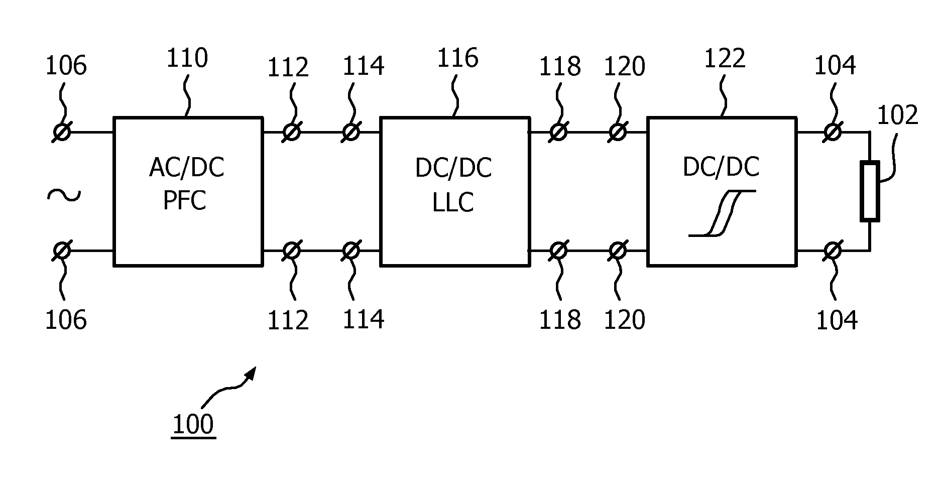
[0018]FIG. 1 depicts a schematic diagram of an embodiment of a power supply circuit 100, connected to a load 102 through output terminals 104. The power supply circuit 100 comprises a first converter stage 110 for converting an AC mains input voltage supplied at input terminals 106 into a DC output voltage (e.g. 430 V) at terminals 112. The first converter stage 110 may be a boost converter, and comprises a rectifier circuit and power factor correction, PFC, circuitry as known per se to the skilled person in various embodiments. If a DC (mains or bus) voltage would be available instead of, or in addition to the AC mains voltage, the first converter stage 110 may be omitted.

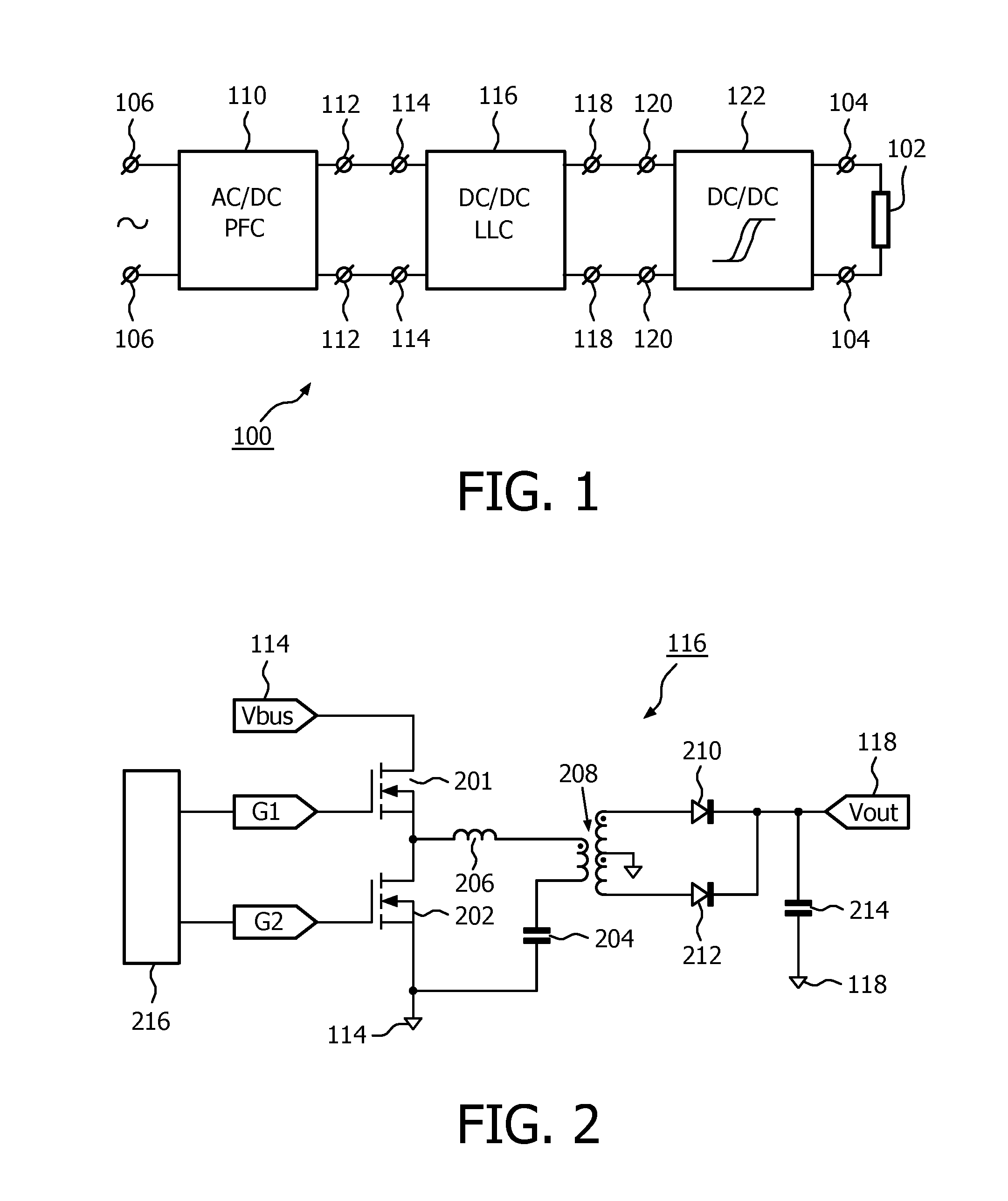
[0019]The DC output voltage of the first converter stage 110 (or a DC mains or bus voltage) is supplied to DC input voltage terminals 114 of a second converter stage, which is also referred to as LLC converter stage 116. The LLC converter stage 116 outputs a DC voltage at output terminals 118. A circuit diagram of...


PUM


Abstract

A power supply circuit has an LLC converter stage for converting a DC voltage input into a DC voltage output, and at least one hysteretic converter stage. Each hysteretic converter stage has a DC voltage input coupled to the DC voltage output of the LLC converter stage, and a DC current output. The LLC converter stage lacks a feedback control, and is operated at its load independent point. A ripple on the DC voltage output of the LLC converter does not affect the output current of the hysteretic converter stage. The stable DC current output of the hysteretic converter stage is coupled to a load having one or more LED strings.

Description

FIELD OF THE INVENTION[0001]The invention relates to the field of power supply circuits and methods, and more specifically to supplying power in a lighting application to a load comprising a plurality of light emitting diodes, LEDs.BACKGROUND OF THE INVENTION[0002]In the field of power supplies, the use of an LLC converter is known. An LLC converter comprises a series arrangement of a first parallel arrangement of a first switch and a first diode, and a second parallel arrangement of a second switch and a second diode. The series arrangement is coupled between a first input terminal and a second input terminal for receiving a DC input voltage. A voltage on the first terminal is positive with respect to a voltage on the second terminal. The cathode of the first diode and the cathode of the second diode are directed to the first terminal. The first diode may be extrinsic, or may be intrinsic to the first switch. Likewise, the second diode may be extrinsic, or may be intrinsic to the s...

Claims


Application Information

Patent Timeline
Patent Type & Authority Applications(United States)
IPC IPC(8): H05B37/02H02J1/00H02M3/335
CPCH02M1/4225H02M3/335H05B33/0815Y02B70/126H02M2001/007Y02B70/10H05B45/3725H05B45/375H05B45/38H02M1/007H02J9/062H02M3/33561H02M3/33584Y02B20/30
Inventor VAN DER VEEN, GEERT WILLEMSNELTEN, JEROEN
Owner SIGNIFY HLDG BV
Why Eureka
Try Eureka