Semiconductor device

a semiconductor and device technology, applied in the field of semiconductor devices, can solve the problems of increasing the chip area of a memory chip, difficult to dramatically increase the storage capacity per chip (or per memory chip), and difficult to speed up the transistor of the front-end portion

Active Publication Date: 2012-05-10
LONGITUDE LICENSING LTD
View PDF3 Cites 17 Cited by
  • Summary
  • Abstract
  • Description
  • Claims
  • Application Information

AI Technical Summary

Benefits of technology

[0014]According to the present invention, in the first chip (interface chip) that receives the first command signal, the first command signal is delayed to generate the second command signal. The generated second command signal is supplied to the second chip (core chip). Therefore, there is no need to provide a circuit that delays the first command signal in the second chip. Accordingly, it is unnecessary to supply the clock signal from the first chip to the second chip. Therefore, particularly in a semiconductor device of a type that uses a through silicon via to interconnect a plurality of chips, it is possible to solve the above problems.

Problems solved by technology

Therefore, it is difficult to dramatically increase the storage capacity per chip (or per memory chip).
Another problem is that even though a circuit that makes up the front-end portion is a logic circuit, the back-end portion containing a memory core is produced at the same time as the front-end portion, making it difficult to speed up a transistor of the front-end portion.
Therefore, the problem is that the chip area of a memory chip increases.
Therefore, for example, when the clock signal is commonly supplied from an interface chip to a plurality of core chips, parasitic capacitance components and parasitic resistance components of a clock line could distort the waveform, possibly making it difficult to count the latency.
As a result, the above problems become more serious.
Even when a resistance value of the through silicon via is higher than a design value for some reason, the above problems become more serious.

Method used


Image

  • Semiconductor device
  • Semiconductor device
  • Semiconductor device

Examples


Embodiment Construction

[0034]Preferred embodiments of the present invention will be explained below in detail with reference to the accompanying drawings.

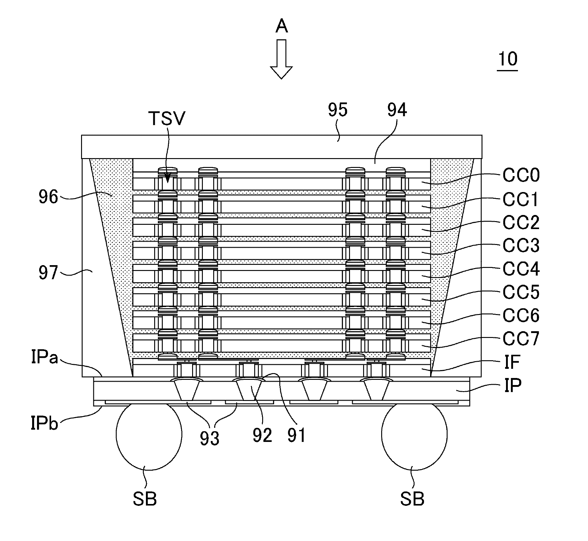
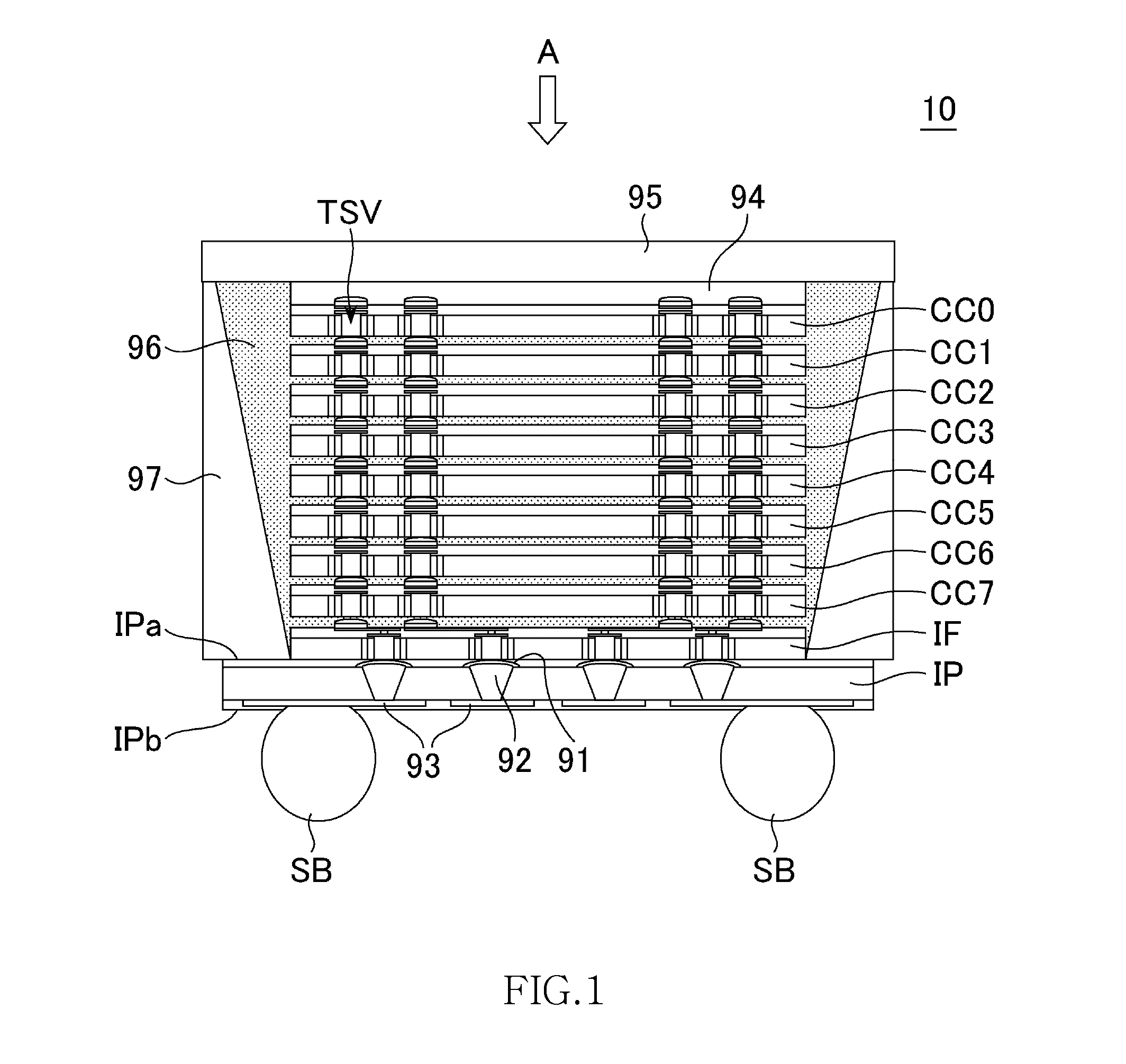
[0035]FIG. 1 is a schematic cross-sectional view provided to explain the structure of a semiconductor device 10 according to the preferred embodiment of the present invention.

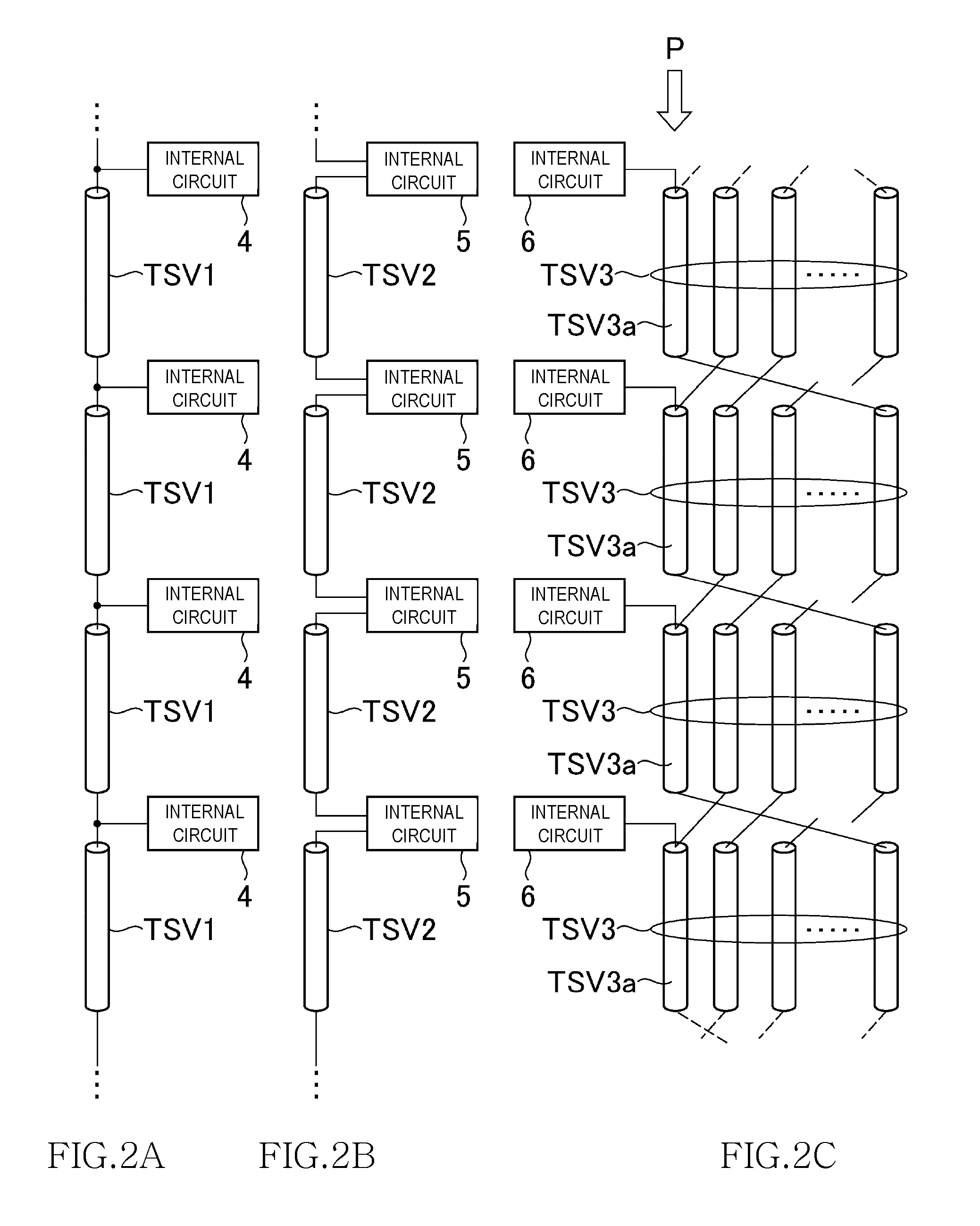
[0036]As shown in FIG. 1, the semiconductor device 10 according to this embodiment has the structure where 8 core chips CC0 to CC7 that have the same function and structure and are manufactured using the same manufacture mask, an interface chip IF that is manufactured using a manufacture mask different from that of the core chips CC0 to CC7 and an interposer IP are laminated. The core chips CC0 to CC7 and the interface chip IF are semiconductor chips using a silicon substrate and are electrically connected to adjacent chips in a vertical direction through plural Through Silicon Vias (TSV) penetrating the silicon substrate. The through silicon via may be referred to as a penetration ...


PUM


Abstract

A semiconductor device includes: an interface chip including a read timing control circuit that outputs, in response to a command signal and a clock signal supplied from the outside, a plurality of read control signals that are each in synchronization with the clock signal and have different timings; and core chips including a plurality of internal circuits that are stacked on the interface chip and each perform an operation indicated by the command signal in synchronization with the read control signals. According to the present invention, it is unnecessary to control latency in the core chips and therefore to supply the clock signal to the core chips.

Description

BACKGROUND OF THE INVENTION[0001]1. Field of the Invention[0002]The present invention relates to a semiconductor device, and particularly to a semiconductor device in which a front-end portion having an interface function and a back-end portion containing a memory core are integrated onto separate semiconductor chips.[0003]2. Description of Related Art[0004]A storage capacity required for a semiconductor memory device, such as DRAM (Dynamic Random Access Memory), has been growing over years. To meet the requirement, in recent years, a memory device called multichip package, in which a plurality of memory chips is stacked, has been proposed. However, memory chips used in the multichip package are typical, stand-alone memory chips. Therefore, the memory chips each contain a front-end portion that provides an interface with an external section (which is for example a memory controller). Accordingly, an occupied space that can be allocated to a memory core in each memory chip is limited...

Claims


Application Information

Patent Timeline
Patent Type & Authority Applications(United States)
IPC IPC(8): H04L7/00
CPCG11C5/025G11C5/063G11C11/4082G11C11/408H01L2224/16145G11C11/4076G11C11/4087
Inventor HAYASHI, JUNICHI
Owner LONGITUDE LICENSING LTD
Why Eureka
Try Eureka