Repetitive pressure-pulse apparatus and method for cavitation damage research

a cavitation damage and pressure-pulse technology, applied in the field of cavitation damage research, can solve problems such as cavitation damage on the surface of test specimens, and achieve the effect of accurate imitation of cavitation

Inactive Publication Date: 2012-05-17
UT BATTELLE LLC
View PDF7 Cites 8 Cited by
  • Summary
  • Abstract
  • Description
  • Claims
  • Application Information

AI Technical Summary

Benefits of technology

[0007]The present invention provides a compact, portable, repetitive pressure-pulse system, using laser induced shock wave, to accurately mimic cavitation.
[0012]The short pulse duration of the pulse laser, normally in a 5-20 ns range, is more efficient in generating shock waves compared to the stationary wave pattern generated by ultrasonic devices. The developed novel system have many distinctive advantages for cavitation research; in particular: (i) it may have no external driver (pump) or moving part; (ii) the relatively small design can avoid the lengthy and large water channel loop required in conventional approaches; (iii) it can be tailored to multiple design variables to realistically mimic cavitation environments such as high temperature, high pressure, and corrosive media; (iv) it can have low testing time and cost. The present apparatus provides an expedient tool and methodology to benchmark cavitation damage, estimate structural material lifetime, and assist the development of optimized advanced system approaches or materials to mitigate cavitation damage.

Problems solved by technology

The laser may generate a shock wave within the cavitation media, which resonates from the focal point of the laser through the interior chamber and creates cavitation damage on the surface of the test specimen.

Method used


Image

  • Repetitive pressure-pulse apparatus and method for cavitation damage research
  • Repetitive pressure-pulse apparatus and method for cavitation damage research
  • Repetitive pressure-pulse apparatus and method for cavitation damage research

Examples


Embodiment Construction

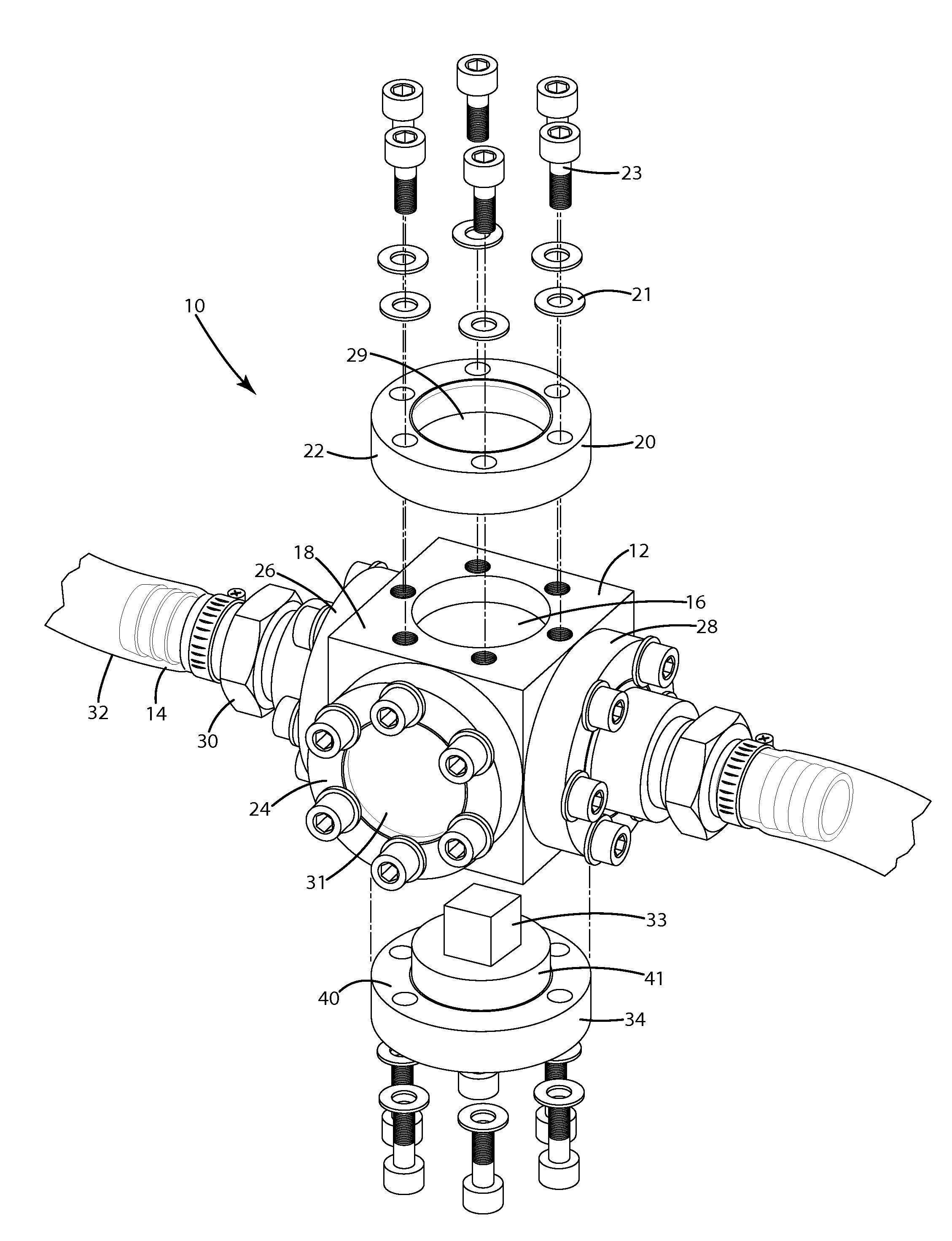
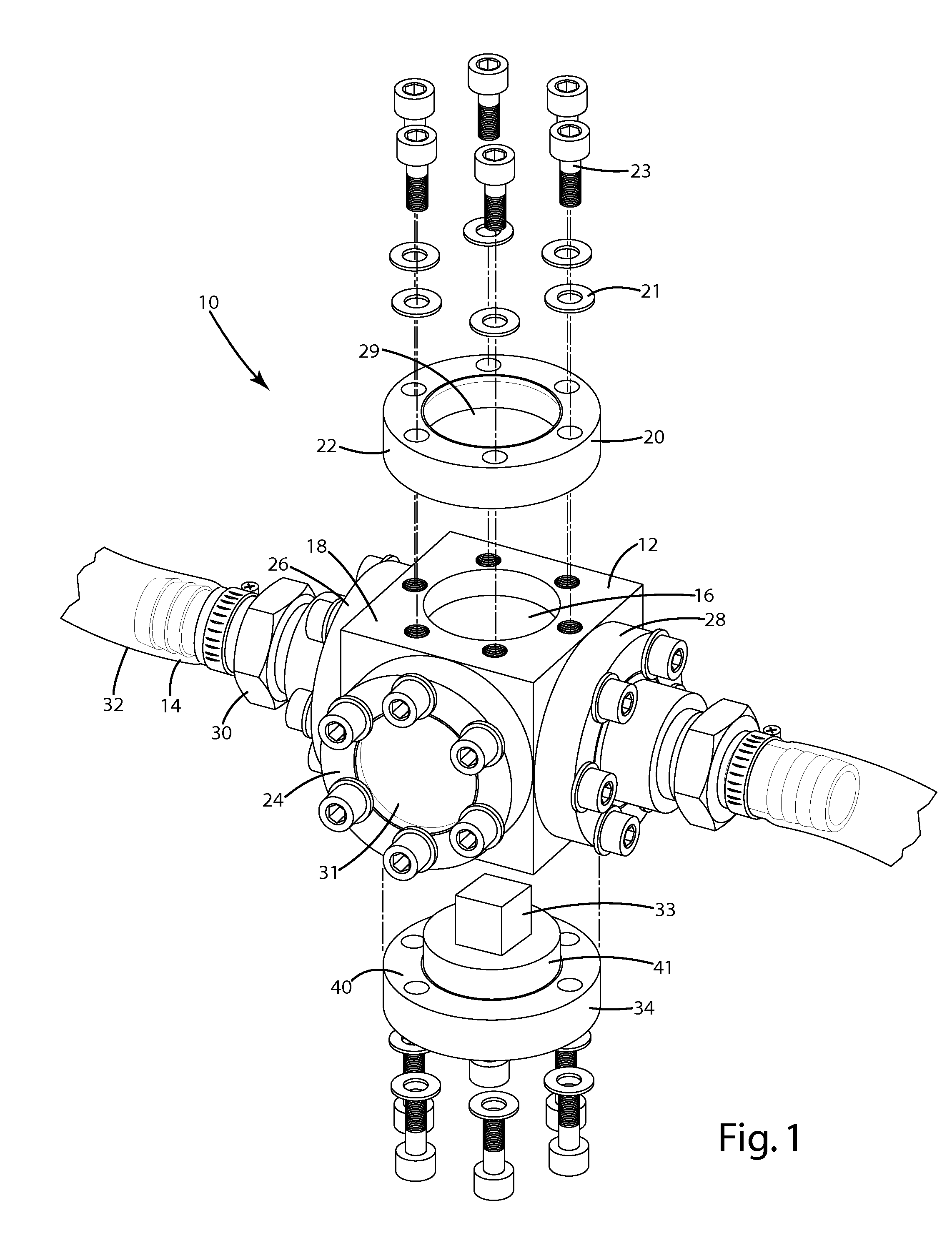
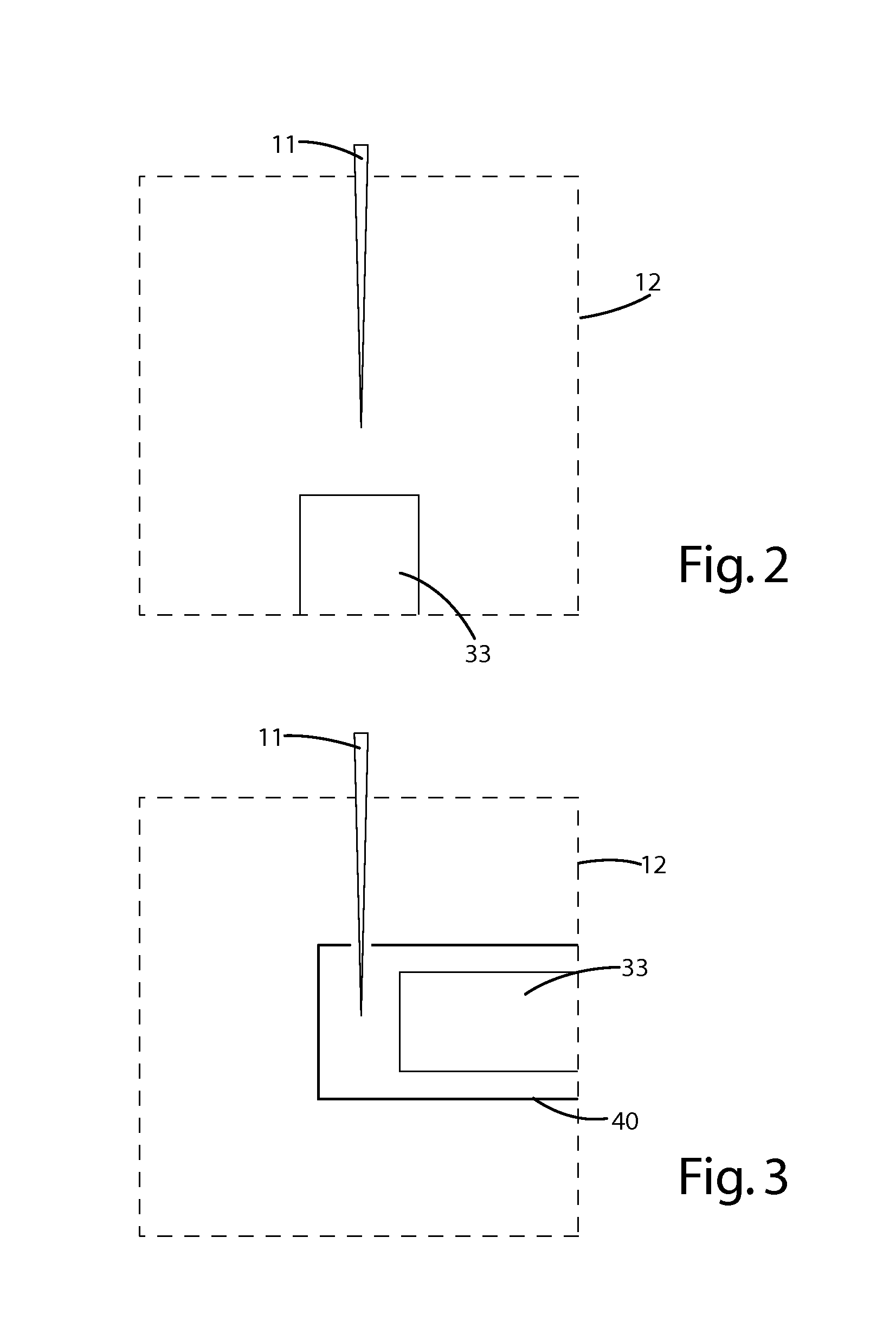
[0027]A system for generating cavitation and cavitation damage on a test sample is shown in FIG. 1 and generally designated 10. In one embodiment, the system includes a cavitation chamber 12 and a liquid system 14 connected to the cavitation chamber 12 for circulating a media, such as water, through the chamber 12. As shown, the cavitation chamber 12 is a 1⅓ inch cube made of stainless steel. There are openings 16, each about ⅝″ in diameter, on each of the six sides 18 of the cube. In one embodiment, six stainless steel cylindrical-end disks 20 coupled with copper washers 21 are used to seal the openings 16 in the cube to form the cavitation chamber 12.

[0028]The top end disk 22 of the chamber 12 may include a transparent quartz window 29 for laser passage and the front end disk 24 may include a glass viewport 31 to enable viewing of the interior of the chamber 12. The left 26 and the right 28 end disks may include fitting nozzles 30 connected to water tubing 32. The bottom end disk ...


PUM

PropertyMeasurementUnit
frequencyaaaaaaaaaa
wave lengthaaaaaaaaaa
Poweraaaaaaaaaa

Abstract

An apparatus for inducing cavitation at a surface of a specimen includes a cavitation chamber, a window extending through the wall of the chamber to an area outside the chamber, a test specimen positioned within the chamber, and a cavitation media inside the chamber and in contact with the surface of the specimen. A laser light source is disposed outside the chamber, and is operable to provide a laser beam through the window and into the cavitation media. The laser light source generates a shock wave in the cavitation media, the shock wave causing cavitation at the surface of the specimen.

Description

[0001]This invention was made with government support under Contract No. DE-AC05-00OR22725 awarded by the U.S. Department of Energy. The government has certain rights in the invention.BACKGROUND OF THE INVENTION[0002]Cavitation is the process of the formation of vapor, void, or bubbles due to pressure changes in a liquid flow. The motion, and eventual collapse of the bubbles can cause local pressure changes in the liquid, which can be transmitted to a target surface either in the form of a shock wave, or by micro-jets, depending on the bubble-surface distance. Pressure greater than 100,000 psi has been measured in a shock wave resonating from cavitating bubbles. It is generally understood that the cycle of formation and collapse of the bubbles that occurs, often at a high frequency, can generate dynamic stress on the surfaces of objects; ultimately the dynamic stress can contribute to the fatigue of the target surface, including micro-cracks that form and coalesce on the surface, ev...

Claims


Application Information

Patent Timeline
Patent Type & Authority Applications(United States)
IPC IPC(8): F17D1/08H05B7/18
CPCH05B7/18F17D1/08G01N3/567G01N33/2823G01N2203/0055Y10T137/0391B23K26/122E21B43/26E21B49/006G01N29/2418
Inventor WANG, JY-ANREN, FEILIU, YUN
Owner UT BATTELLE LLC
Why Eureka
Try Eureka