
Electrically-heated catalyst

Active Publication Date: 2012-05-17
TOYOTA JIDOSHA KK
View PDF1 Cites 19 Cited by
  • Summary
  • Abstract
  • Description
  • Claims
  • Application Information

AI Technical Summary

Benefits of technology

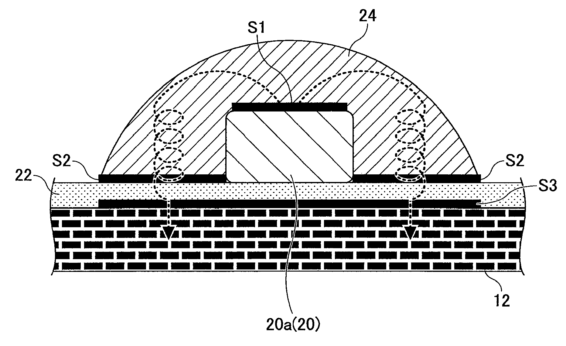
[0006]The present invention is made in consideration of the matters as described above, and it is an object of the present invention to provide an electrically-heated catalyst in which the cracks or ruptures of the electrodes can be prevented by reducing the thermal stress due to the difference in the coefficients of thermal expansion between the carrier and the electrodes.
[0008]According to the present invention, the cracks or ruptures of the comb-shaped electrode portions can be prevented by reducing the thermal stress due to the difference in the coefficients of thermal expansion between the carrier and the comb-shaped electrode portions.

Problems solved by technology

Hence, if the electrically-heated catalyst has the configuration in which the carrier and the electrodes whose coefficients of thermal expansion are significantly different from each other are bonded directly, there is a problem that the electrodes tend to peel off from the carrier due to the thermal stress induced in the bonded surface between the electrodes and the carrier, when they are used continuously under a situation where a temperature change occurs.
However, in the configuration in which the electrodes as a whole are bonded to the fixing layer formed by thermal spraying on the underlying layer, the electrodes cannot thermally expand or shrink freely when the thermal stress is induced in the bonding surface between the electrodes and the fixing layer or the bonding surface between the underlying layer and the fixing layer, and thus cracks or ruptures are easily generated at the electrodes, etc.

Method used


Image

  • Electrically-heated catalyst
  • Electrically-heated catalyst
  • Electrically-heated catalyst

Examples


first embodiment

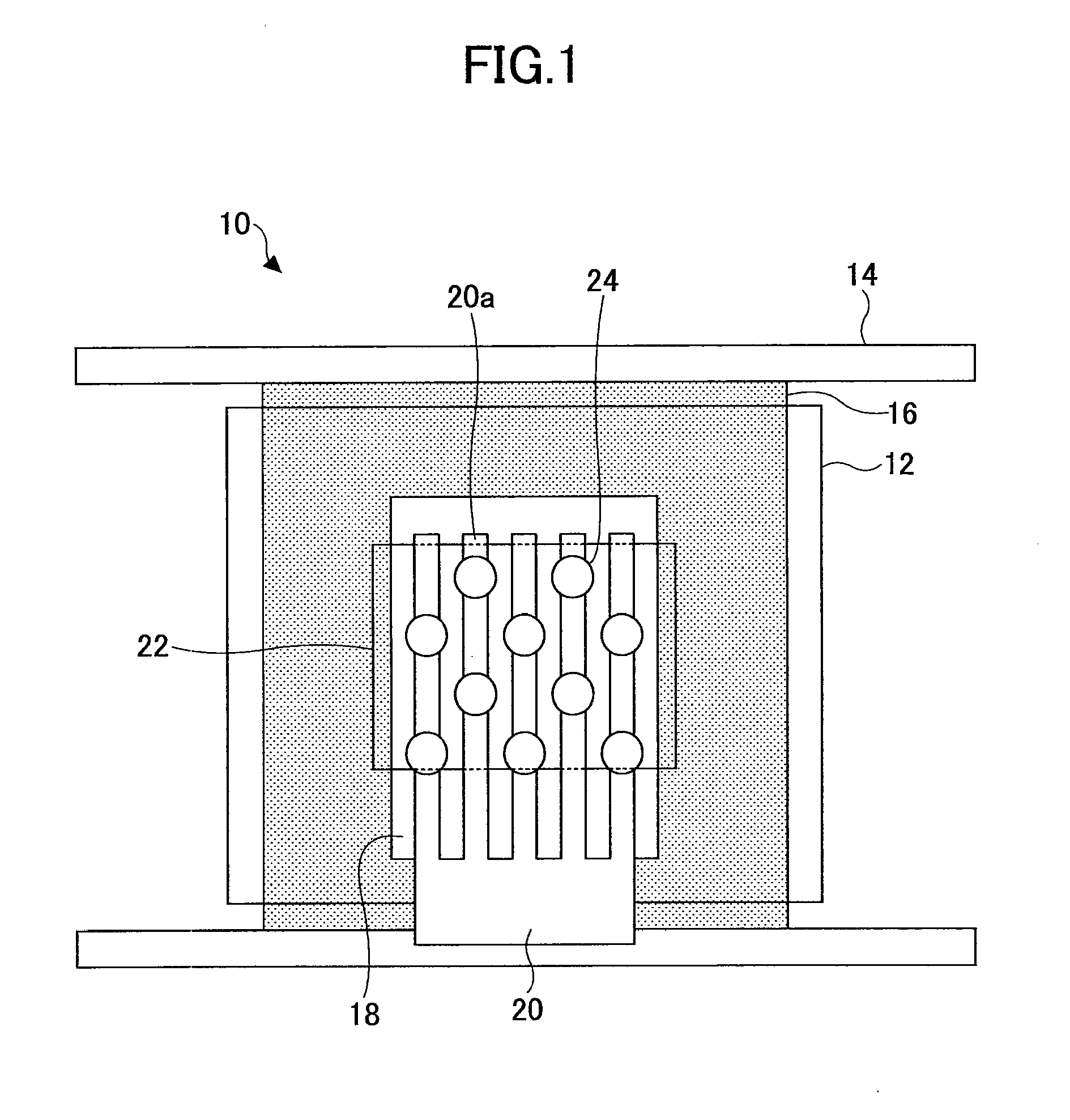
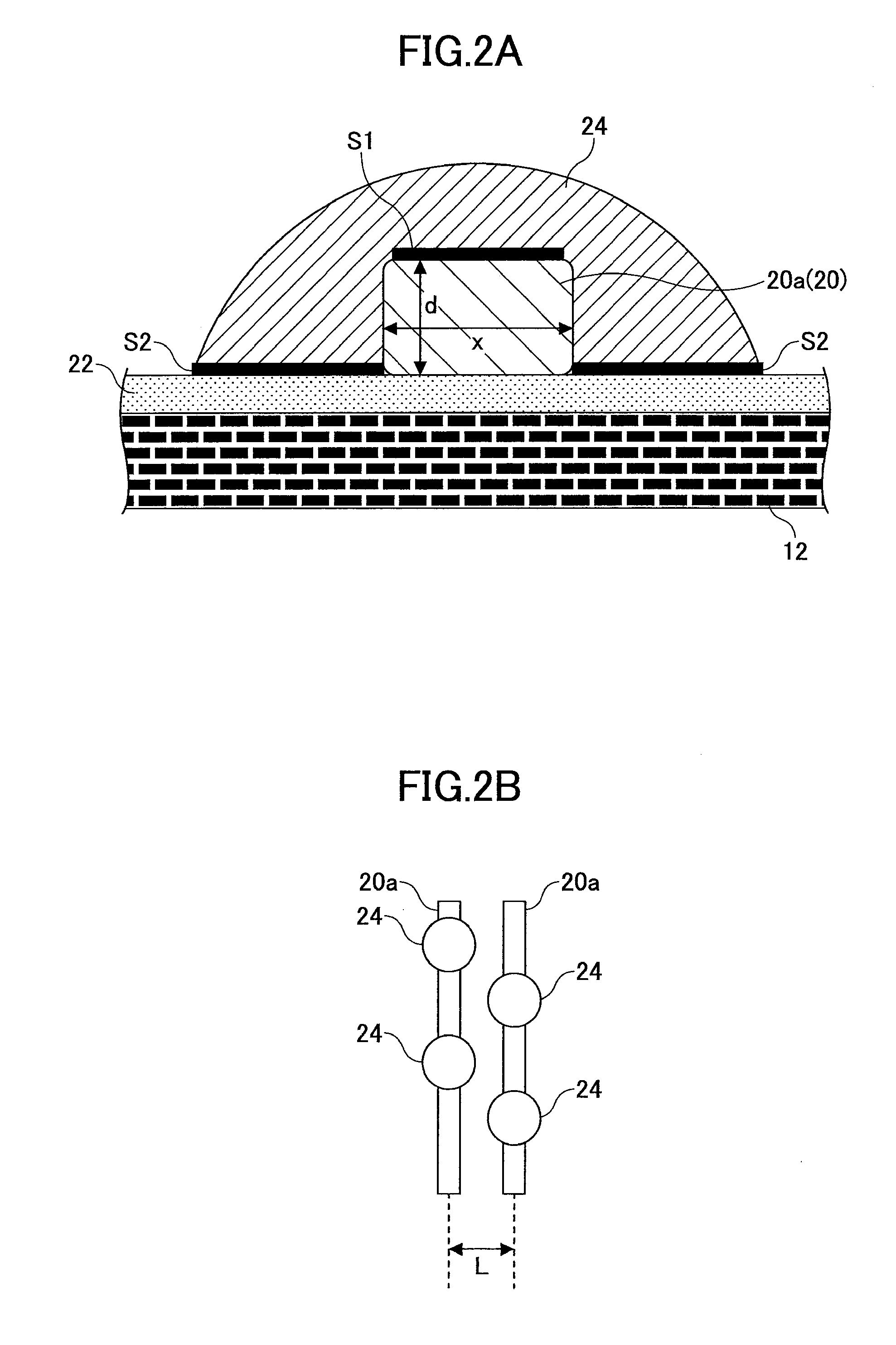
[0026]FIG. 1 is a diagram for illustrating a configuration of an electrically-heated catalyst 10 according a first embodiment of the present invention. FIG. 2A is a cross-sectional view of main portions of the electrically-heated catalyst 10 according the embodiment. Further, FIG. 2B is a top view of main portions of the electrically-heated catalyst 10 according the embodiment. The electrically-heated catalyst 10 according the embodiment is a catalyst for cleaning exhaust gas from a car, etc., and is activated by being heated by energization.

[0027]The electrically-heated catalyst 10 includes a SiC carrier 12 which carries a ceramic catalyst formed of silicon carbide (SiC). The SiC carrier 12 is capable of activating the catalyst by being heated. The SiC carrier 12 is formed in a cylindrical shape. The SiC carrier 12 is held in a casing 14 formed in a cylindrical shape. A mat 16, which functions as electrically insulating layer and thermal insulation layer formed of alumina bulk fibe...

second embodiment

[0045]In the first embodiment as described above, the diameter of the fixing layers 24 is greater than the line width x of the comb-shaped electrode portions 20a, and each of the fixing layers 24 bonds to the corresponding comb-shaped electrode portion 20a and surface portions of the underlying layer 22, which surface portions are located on the opposite sides of the corresponding comb-shaped electrode portion 20a in a direction perpendicular to the longitudinal direction of the corresponding comb-shaped electrode portion 20a. To the contrary, according to the second embodiment, each of the fixing layers bonds to the corresponding comb-shaped electrode portion 20a and only one of surface portions of the underlying layer 22, which surface portions are located on the opposite sides of the corresponding comb-shaped electrode portion 20a in a direction perpendicular to the longitudinal direction of the corresponding comb-shaped electrode portion 20a.

[0046]FIG. 4A is a cross-sectional v...

third embodiment

[0055]In the first and second embodiments as described above, a plurality of fixing layers 24, 102 are provided for each of the comb-shaped electrode portions 20a of the electrode 20 and are placed apart with respect to each other. To the contrary, according to the third embodiment of the present invention, the fixing layers are shared with the neighboring comb-shaped electrode portions 20a in the axial direction of the SiC carrier 12 (i.e., in the direction perpendicular to the longitudinal direction of the comb-shaped electrode portions 20a). In other words, the bonding of the fixing layer to the comb-shaped electrode portions 20a and the underlying layer 22 is performed in such a manner that the fixing layer straddles two comb-shaped electrode portions 20a which are neighboring in the direction perpendicular to the longitudinal direction of the comb-shaped electrode portions 20a.

[0056]FIG. 5A is a cross-sectional view of main portions of an electrically-heated catalyst 200 accor...


PUM

PropertyMeasurementUnit
Electrical conductivityaaaaaaaaaa
Coefficient of linear thermal expansionaaaaaaaaaa

Abstract

An electrically-heated catalyst is disclosed. The catalyst may include a carrier; more than two comb-shaped electrode portions extending in a longitudinal direction; an electrically conductive underlying layer provided between the carrier and the comb-shaped electrode portions; and more than two electrically conductive fixing layers bonding to at least one of the comb-shaped electrode portions and to the underlying layer to fix the comb-shaped electrode portions to the carrier at more than two points spaced apart.

Description

CROSS-REFERENCE TO RELATED APPLICATIONS[0001]The present application is a U.S. continuation application filed under 35 U.S.C. 111(a) and 356(c) of PCT application No. PCT / JP2010 / 070148, filed on Nov. 11, 2010, the entire contents of which are hereby incorporated by reference.TECHNICAL FIELD[0002]The present invention is related to a catalyst. In particular the present invention is related to an electrically-heated catalyst which is energized and heated for effectively cleaning exhaust gas from a car, etc.BACKGROUND ART[0003]An electrically-heated catalyst which is energized and heated for effectively cleaning exhaust gas is known from JP05-115795 A, for example. The electrically-heated catalyst includes a carrier and electrodes attached to the carrier for energizing the carrier. The electrodes supply the carrier with electric power supplied from an external electronic power supply such as a battery. The carrier is activated by being energized via the electrodes to be heated. In this...

Claims


Application Information

Patent Timeline
IPC IPC(8): F01N3/10
CPCB01J35/0033F01N3/2825F01N2450/28Y02T10/26F01N3/2864B01D46/2444F01N3/2013B01J27/224F01N2240/16F01N3/2026B01D53/94Y02T10/12B01J35/33
Inventor KINOSHITA, YASUOIIDA, TATSUOTAKAGAKI, TADASHINAITO, HIDEJIKAJI, GOZOSHIMODA, KENJI
Owner TOYOTA JIDOSHA KK
Learn More