
Thermoelectric stack coating for improved solar panel function

Inactive Publication Date: 2012-05-31
AERIS CAPITAL SUSTAINABLE IP
View PDF11 Cites 39 Cited by
  • Summary
  • Abstract
  • Description
  • Claims
  • Application Information

AI Technical Summary

Benefits of technology

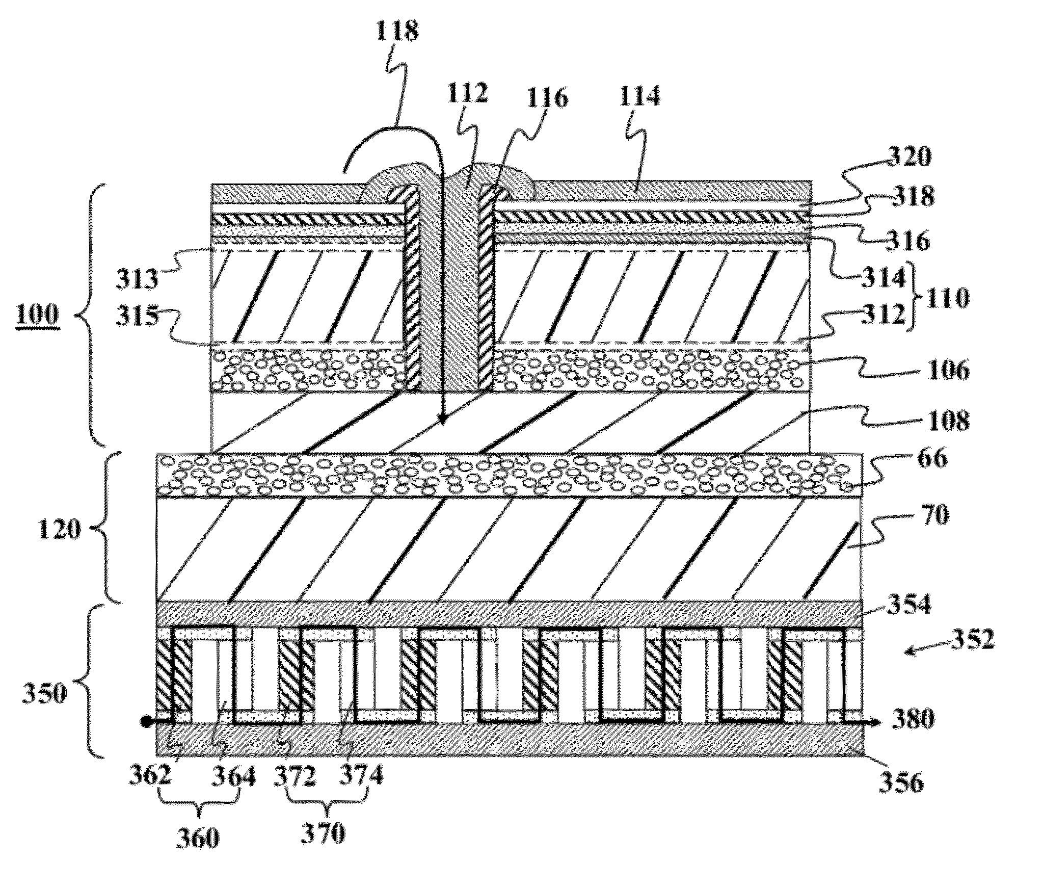
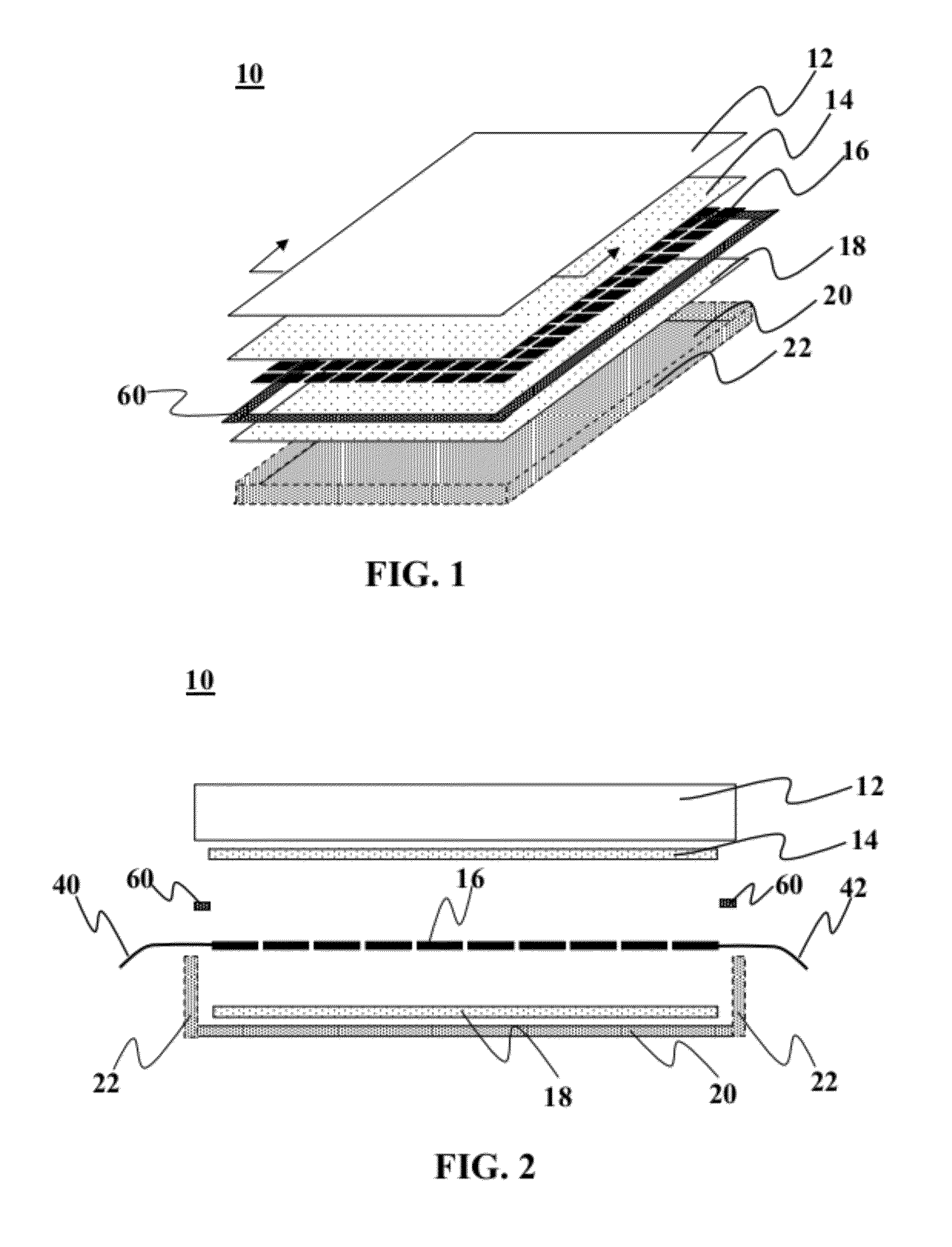
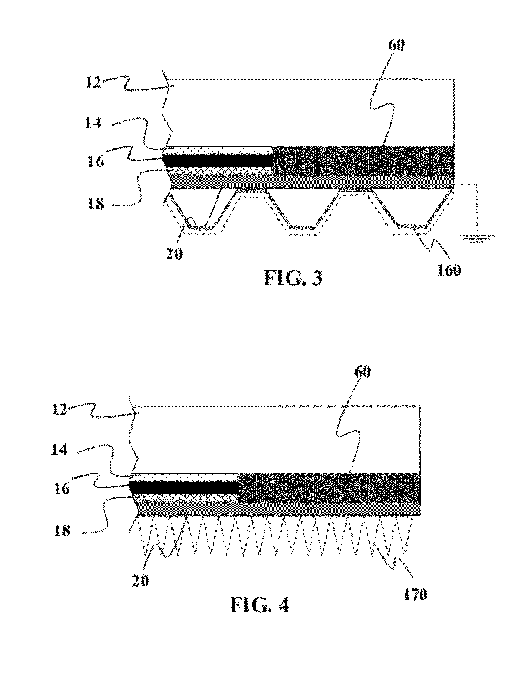
[0005]In one embodiment of the present invention, this enables the front hot solar panel surface to be cooled by attachment of a thermoelectric multilayer stack to the back solar panel surface. The thermoelectric stack cools the solar panel front surface by drawing heat from the front to the back of the panel. That heat is transformed into mechanical vibrations using an inverse Peltier effect and that mechanical energy then transformed into electrical energy using a piezoelectric effect. Power output is first increased by lower operating temperature on front, resulting in a higher power conversion efficiency for the photovoltaic effect taking place in the CIGS / CdS active layers, then from an additional power output from secondary electrical energy created from mechanical arising from the temperature-gradient driven occurrence of the thermoelectric effect. This approach results in two concurrent boosts in power output. It may also extend the life of the solar panel by lowering its average operating temperature, which should increasing its operating lifetime. Although some examples herein describe the use of CIGS / CdS active layers, other active layer such as CdTe, CZTS, silicon, or other materials are not excluded.

Problems solved by technology

Effectively harnessing this potential energy generation technique, however, remains a challenge.

Method used


Image

  • Thermoelectric stack coating for improved solar panel function
  • Thermoelectric stack coating for improved solar panel function
  • Thermoelectric stack coating for improved solar panel function

Examples


embodiment (

Embodiment(s) of the Invention

[0029]One approach to enabling this invention is to (1) create a solar panel whose form factor is comprised of a glass-foil laminate and whose foil back in comprised of Al foil. (2) Placement and / or deposition of a hard ferromagnetic material onto the Al foil. Such a material could be comprised of 1-10 mm of neodymium iron boron (NdFeB). (3) Placement and / or deposition of an elastic, heat conducting material onto the hard magnetic surface. Examples of such material include but are not limited to conductive polymer (e.g., CoolPoly® thermally conductive plastics, PolyOne Therma-Tech thermally conductive plastics, nylon 6-6, filled nylon 6-6, and / or a polyphenylene sulfide, optionally mixed with one or more thermally conductive fillers such as metal, ceramic, graphite, nanotubes, etc.). The material may also incorporate for example, Nylon 1020, Nylon 1040, Nylon 1240, Froton 6165A, Froton 6165D, or polyphenylene sulfide, or any other polymer. The spring co...


PUM


Abstract

Methods and devices for increase power output from solar devices. In one embodiment, the technique enables the front hot solar panel surface to be cooled by attachment of a thermoelectric multilayer stack to the back solar panel surface. The thermoelectric stack cools the solar panel front surface by drawing heat from the front to the back of the panel. That heat is transformed into mechanical vibrations using an inverse Peltier effect and that mechanical energy then transformed into electrical energy using a piezoelectric effect. Power output is first increased by lower operating temperature on front, resulting in a higher power conversion efficiency for the photovoltaic effect taking place in the CIGS / CdS active layers or other thin films, then from an additional power output from secondary electrical energy created from mechanical arising from the temperature-gradient driven occurrence of the thermoelectric effect.

Description

CROSS-REFERENCE TO RELATED APPLICATIONS[0001]This application claims priority to U.S. Provisional Application Ser. Nos. 61 / 373,262 filed Aug. 12, 2010, 61 / 373,265 filed Aug. 12, 2010, 61 / 375,230 filed Aug. 19, 2010, 61 / 375,793 filed Aug. 20, 2010, and 61 / 405,043 filed Oct. 20, 2010. All of the foregoing applications are fully incorporated herein by reference for all purposes.FIELD OF THE INVENTION[0002]This invention relates to methods and devices for increasing electrical power output from devices such as but not limited to solar panels and solar cells.BACKGROUND OF THE INVENTION[0003]Thermo-electrical devices convert thermal energy into electrical energy, by means of the Seebeck effect, also called the inverse Peltier effect, which was discovered by Seebeck in 1821. Effectively harnessing this potential energy generation technique, however, remains a challenge.SUMMARY OF THE INVENTION[0004]The disadvantages associated with the prior art are overcome by some or all embodiments of t...

Claims


Application Information

Patent Timeline
IPC IPC(8): H01L31/058
CPCY02E10/50H02S10/10H01L31/0583H02N10/00
Inventor SAGER, BRIAN M.
Owner AERIS CAPITAL SUSTAINABLE IP
Learn More