Printing apparatus for manufacturing a spacer and method of manufacturing a display panel

a printing apparatus and spacer technology, applied in the manufacture of electrode systems, electric discharge tubes/lamps, instruments, etc., can solve the problems of reducing display quality and non-uniform coating of spacers on the substrate, so as to improve display quality, enhance press characteristics, and prevent smear defects when the display panel is pressed

Active Publication Date: 2012-05-31
SAMSUNG DISPLAY CO LTD
View PDF3 Cites 3 Cited by
  • Summary
  • Abstract
  • Description
  • Claims
  • Application Information

AI Technical Summary

Benefits of technology

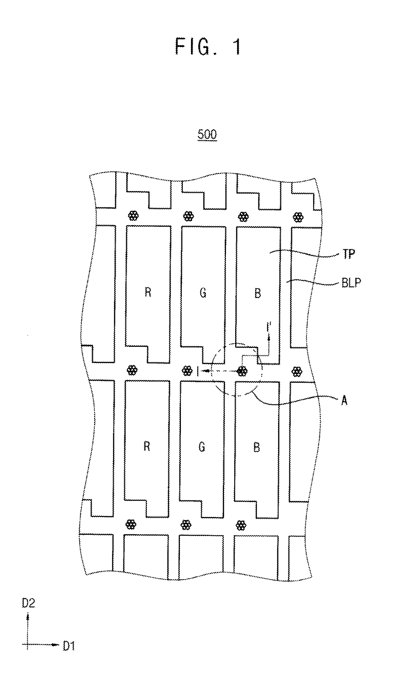
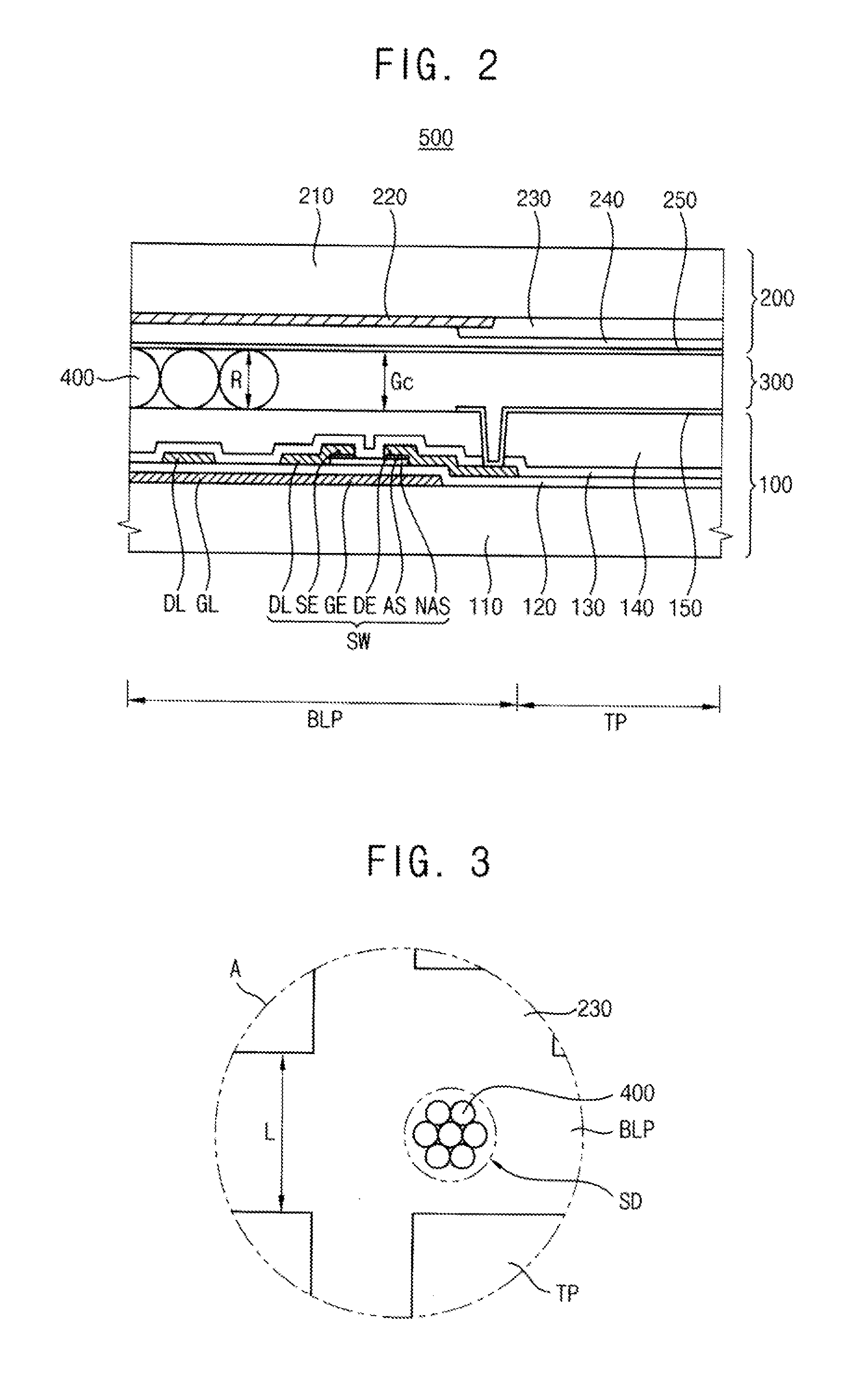
[0019]According to a printing apparatus for manufacturing a spacer and a method of manufacturing a display panel, the received number of spacers per unit area of the receiving recess may be increased, and the spacers may be more uniformly provided to each of plural receiving recesses. Thus, the spacers may maintain a distance between the first and second substrates more stably, so that press characteristics may be enhanced and smear defects occurring when the display panel is pressed may be prevented. Moreover, the distance between the first and second substrates may be maintained more uniformly, so that the display quality of the display panel may be improved.

Problems solved by technology

However, concave portions of the printing plate often do not pick up any beads, which often results in a non-uniform coating of spacers on the substrate, where some areas contain an insufficient number of spacers.
This results in areas of the substrate in which the cell gap cannot be maintained, or is easily collapsed, resulting in display defects such as spots or flickers, which reduce display quality.

Method used


Image

  • Printing apparatus for manufacturing a spacer and method of manufacturing a display panel
  • Printing apparatus for manufacturing a spacer and method of manufacturing a display panel
  • Printing apparatus for manufacturing a spacer and method of manufacturing a display panel

Examples


experiment 1

[0075]Five printing plates were made, each of which has elliptical receiving recesses with a depth of about 2.7 μm, where the recesses of each plate have a short axis length / long axis length of 10.5 μm / 15.75 μm, 13.5 μm / 20.25 μm, 16.5 μm / 24.75 μm, 19.5 μm / 29.25 μm and 22.5 μm / 33.75 μm, respectively. After ball-shaped beads with a diameter of about 3.35 μm were infiltrated into one receiving recess, an average number of beads actually infiltrated into this receiving recess was measured. The measured result is presented in FIG. 15 as Experiment 1.

experiment 2

[0076]Five printing plates substantially identical to those of Experiment 1 were prepared. After ball-shaped beads with a diameter of about 3.4 μm were infiltrated into one receiving recess, and an average number of beads actually infiltrated into this receiving recess was measured. The measured result is presented in FIG. 15 as Experiment 2.

experiment 3

[0084]Five printing plates were prepared, each having plural elliptical receiving recesses. The recesses of each plate have a depth of about 2.7 μm, and a short axis length / long axis length of 10.5 μm / 15.75 μm, 13.5 μm / 20.25 μm, 16.5 μm / 24.75 μm, 19.5 μm / 29.25 μm and 22.5 μm / 33.75 μm, respectively. After ball-shaped beads with a diameter of about 3.35 μm were infiltrated into one receiving recess, an average number of beads actually infiltrated into the receiving recess was measured. Then, the beads were transferred onto the printing roller by rolling the printing roller over the printing plate, and an average number of beads actually remaining on the printing plate was measured. A ratio of the number of beads remaining on the printing plate to the number of beads infiltrated on the printing plate will be defined as “bead number ratio.” The bead number ratio may be calculated in accordance with diameters of the receiving recesses, and then the result thereof is presented in FIG. 16....


PUM

PropertyMeasurementUnit
lengthaaaaaaaaaa
lengthaaaaaaaaaa
lengthaaaaaaaaaa

Abstract

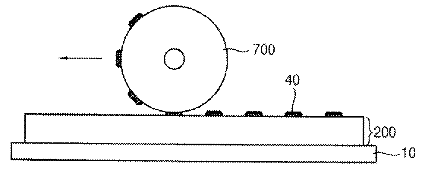
A printing apparatus for manufacturing a spacer includes a printing plate and a printing roller. The printing plate has a plurality of receiving recesses formed thereon. The receiving recess has a generally elliptical shape. The receiving recesses are infiltrated with a plurality of beads. The printing roller transfers the beads onto its outer surface by rolling over the receiving recesses, and transfers the beads from its outer surface onto an external substrate. Thus, the spacers may maintain a distance between the first and second substrates stably, so that press characteristics may be enhanced and smear defects occurring when the display panel is pressed may be prevented.

Description

PRIORITY STATEMENT[0001]This application claims priority under 35 U.S.C. §119 to Korean Patent Application No. 2010-120232, filed on Nov. 30, 2010 in the Korean Intellectual Property Office (KIPO), the contents of which are herein incorporated by reference in their entirety.BACKGROUND OF THE INVENTION[0002]1. Field of the Invention[0003]Example embodiments of the present invention relate generally to flat panel display fabrication. More specifically, example embodiments of the present invention relate to printing apparatuses for manufacturing a spacer, and methods of manufacturing a display panel.[0004]2. Description of the Related Art[0005]Generally, a liquid crystal display (“LCD”) device includes an LCD panel displaying images by controlling the transmittance of a liquid crystal layer, and a light providing assembly providing light to the LCD panel. The LCD panel includes a first substrate on which a thin-film transistor (“TFT”) is formed to act as a switching element, and a seco...

Claims


Application Information

Patent Timeline
Patent Type & Authority Applications(United States)
IPC IPC(8): G02F1/1341B32B37/12H01J9/00B05C1/00
CPCB32B38/145G02F1/13394B32B2457/202
Inventor JANG, DAE-HWANKIM, MIN-UKAN, MOON-JUNGJO, GUG-RAEKIM, KYU-YOUNG
Owner SAMSUNG DISPLAY CO LTD
Why Eureka
Try Eureka