Regenerative Hydraulic Pump

a hydraulic pump and regenerative technology, applied in the direction of piston pumps, fluid couplings, hybrid vehicles, etc., can solve the problems that the compliant spring constant cannot generate the resistance to produce the required pressure in high pressure/low flow operating states, and the soft spring constant cannot generate the resistance needed to achieve the effect of pressur

Inactive Publication Date: 2012-06-07
SARCOS LC
View PDF0 Cites 32 Cited by
  • Summary
  • Abstract
  • Description
  • Claims
  • Application Information

AI Technical Summary

Benefits of technology

[0010]In light of the problems and deficiencies inherent in the prior art, the present invention seeks to overcome these by providing a regenerative hydraulic pumping system which allows the internal combustion engine to run continuously and efficiently at high speed in between periods of pumping demand, so that the power and torque of the engine is instantaneously available when needed. By running the engine continuously at high speed regardless of the operating state of the hydrau

Problems solved by technology

But this same soft, compliant spring constant cannot generate the necessary resis

Method used


Image

  • Regenerative Hydraulic Pump
  • Regenerative Hydraulic Pump
  • Regenerative Hydraulic Pump

Examples


Embodiment Construction

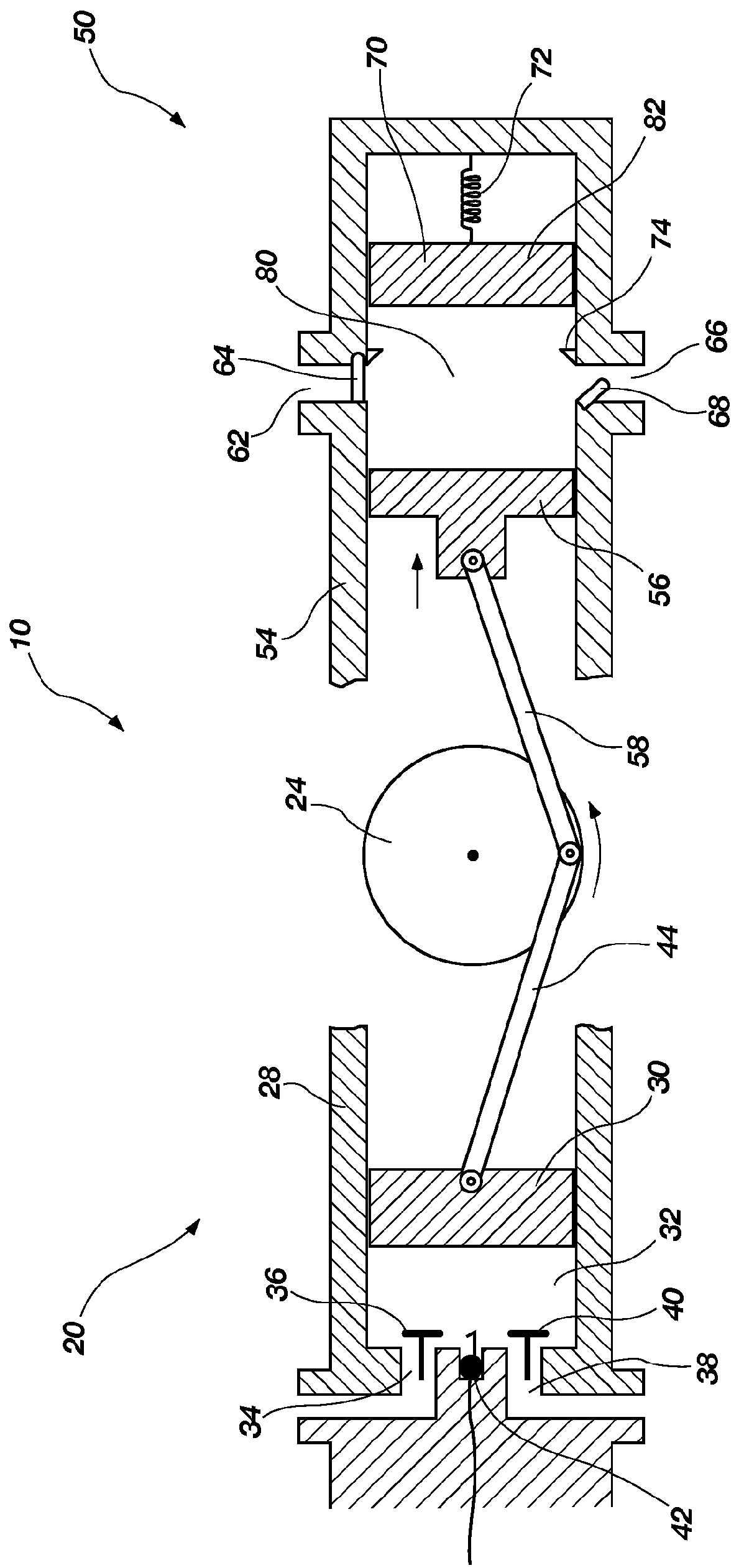
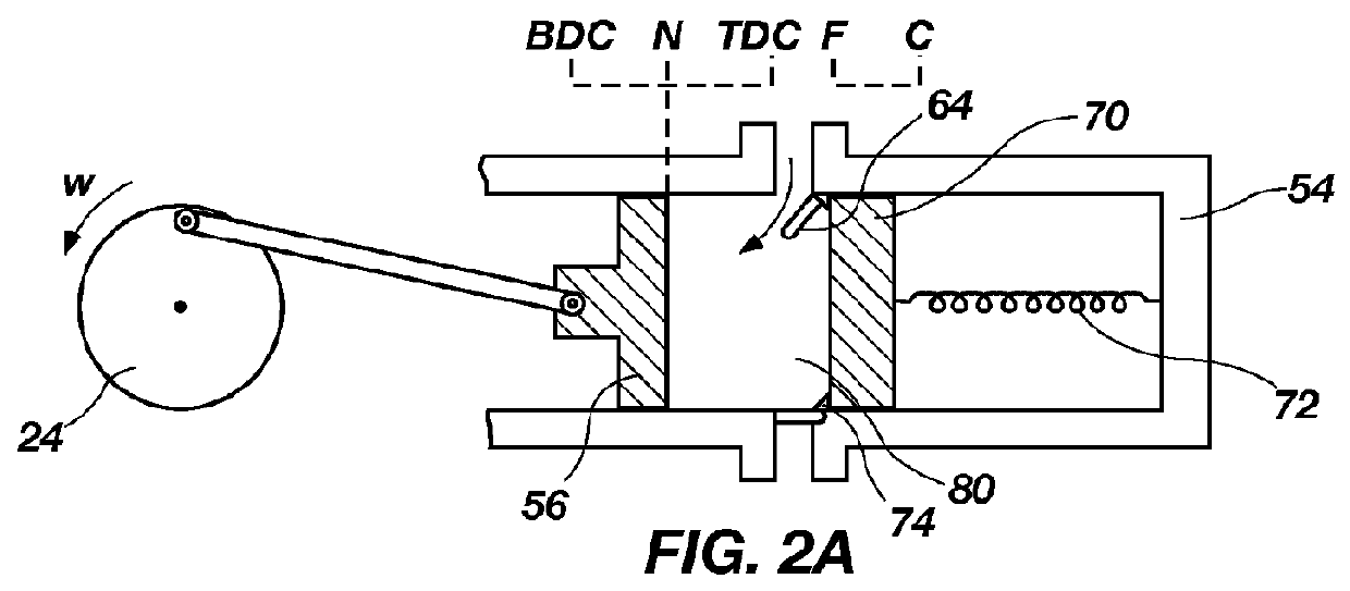
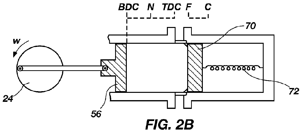
[0035]The following detailed description of exemplary embodiments of the invention makes reference to the accompanying drawings, which form a part hereof and in which are shown, by way of illustration, exemplary embodiments in which the invention may be practiced. While these exemplary embodiments are described in sufficient detail to enable those skilled in the art practice the invention, it should be understood that other embodiments may be realized and that various changes to the invention may be made without departing from the spirit and scope of the present invention. Thus, the following more detailed description of the embodiments of the present invention, as represented in FIGS. 1 through 9, is not intended to limit the scope of the invention, as claimed, but is presented for purposes of illustration only and not limitation to describe the features and characteristics of the present invention, to set forth the best mode of operation of the invention, and to sufficiently enabl...


PUM


Abstract

A regenerative hydraulic pump that allows for efficient operation of a hydraulic system under high pressure/low flow conditions that comprises a crankshaft providing a rotating inertial mass, and a regenerative hydraulic pump cylinder that comprises a pump cylinder housing, a pump piston mechanically connected to the crankshaft; and a compliant pressure chamber that stores a portion of the energy extracted by the pump piston during a pumping stroke for release back to the pump piston and to the crankshaft during a regenerative back stroke.

Description

FIELD OF THE INVENTION[0001]The present invention relates generally to internal combustion engines, and to hydraulic pumping systems that extract energy from an internal combustion or other type of engine or motor-driven rotating crankshaft, and that convert such energy into usable energy or work.BACKGROUND OF THE INVENTION AND RELATED ART[0002]There are many different types of primary power sources available that convert fossil and other fuels into usable energy or power designed to perform work for one or more purposes. Some of the applications utilizing such power sources include everyday common items, such as motor vehicles, lawn mowers, generators, hydraulic systems, etc. Perhaps the best known example of a primary power source is the well known internal combustion engine, which converts the energy obtained or generated from the combustion of fossil fuel into usable energy, such as mechanical energy, electrical energy, hydraulic energy, etc. Indeed, an internal combustion engin...

Claims


Application Information

Patent Timeline
IPC IPC(8): F16D31/02
CPCB60K6/12F02B63/06F02B67/08F04B1/0421Y02T10/6208F04B9/045F04B17/05F04B49/16F04B53/162F04B1/053F04B11/0016F04B11/0033Y02T10/62
Inventor JACOBSEN, STEPHEN C.MCCULLOUGH, JOHNOLIVIER, MARC X.SMITH, FRASER M.
Owner SARCOS LC
Why Eureka
Try Eureka