Refrigerator

a technology of refrigerators and cooling chambers, which is applied in the field of refrigerators, can solve the problems of many refrigerants currently used in vapor-compression refrigeration systems that may have a negative environmental impact, and the large-scale commercialization has not happened, so as to reduce the temperature of working fluids, increase the heat removal time period, and simple mechanical structure

Inactive Publication Date: 2008-06-26
CAO YIDING
View PDF5 Cites 6 Cited by
  • Summary
  • Abstract
  • Description
  • Claims
  • Application Information

AI Technical Summary

Benefits of technology

[0007]It is therefore an objective of this invention to provide a refrigerator using a gas, such as air, as the working fluid based on well-developed technologies, in particular the basic structure of a reciprocating compressor. The invention combines the compression functionality of a compressor and the expansion functionality of a turbine in an air cycle machine into a single refrigerator unit having a simple mechanical structure, and provides a significantly increased heat removal time period before the expansion stroke to reduce the temperature of the working fluid under a substantially constant volume without increasing the number of strokes per discharge in a cycle. Said refrigerator system comprises at least a piston and cylinder assembly including a piston reciprocatingly mounted within the cylinder space, and at least two cooling chambers associated with each cylinder. Each said cooling chamber has therewithin a heat exchanger unit that facilitates heat transfer from the working fluid to a heat sink or cooling fluid within said chamber, a port leading to said cylinder space, and a cooling-chamber valve, said valve opening or closing said port to establish or block communication between said chamber and cylinder space. Said refrigerator is adapted to operate on a cycle having 4n essential strokes for a refrigerator utilizing intake and discharge strokes for respective intake and discharge purposes, or 2n essential strokes for a refrigerator utilizing a scavenging process for discharge and intake purposes, where n is the number of cooling chambers associated with each cylinder. For a refrigerator having intake and discharge strokes, each said cooling chamber has an associated compression stroke, an expansion stroke, and between said compression and expansion strokes a time period of 4(n-1) strokes available for heat transfer from the working fluid enclosed within the cooling chamber to the heat sink. For a refrigerator utilizing a scavenging process for discharge and intake, each said cooling chamber has an associated compression stroke, an expansion stroke, and between said compression and expansion strokes a time period of 2(n-1) strokes available for heat transfer from the working fluid enclosed within the cooling chamber to the heat sink. In both cases, during the time period of heat transfer between the enclosed working fluid and heat sink, said piston would provide strokes for the working fluid associated with another cooling chamber. As a result, the refrigerator thus constructed may fulfill many basic operational requirements of an Otto refrigeration cycle that is the reverse of an Otto power cycle. The refrigerator may be relatively compact and inexpensive with a sufficiently large cooling capacity and a theoretical coefficient of performance (COP) comparable to that of a vapor-compression refrigerator. Moreover, the need of using a man-made chemical compound as the working fluid is eliminated.
[0009]Yet another objective is to provide a compact and convenient cooling means as a heat exchanger unit for said cooling chamber, said cooling means may be a heat pipe heat exchanger system.

Problems solved by technology

Although other types of refrigeration systems such as absorption and jet ejector refrigeration systems have been developed, due to a lower coefficient of performance (COP), their uses are limited to certain applications where thermal energy is abundant.
However, it is well known that many refrigerants currently used in vapor-compression refrigeration systems may have a negative environmental impact related to ozone layer depletion and global warming.
Although the gas refrigeration system mentioned above has found some applications in niche markets, large-scale commercialization has not happened so far due to its low coefficient of performance, bulky size, and high costs.
The linkage between the turbine and the compressor to transmit expansion work from the turbine to the compressor may also represent a challenge.

Method used


Image

  • Refrigerator
  • Refrigerator
  • Refrigerator

Examples


Embodiment Construction

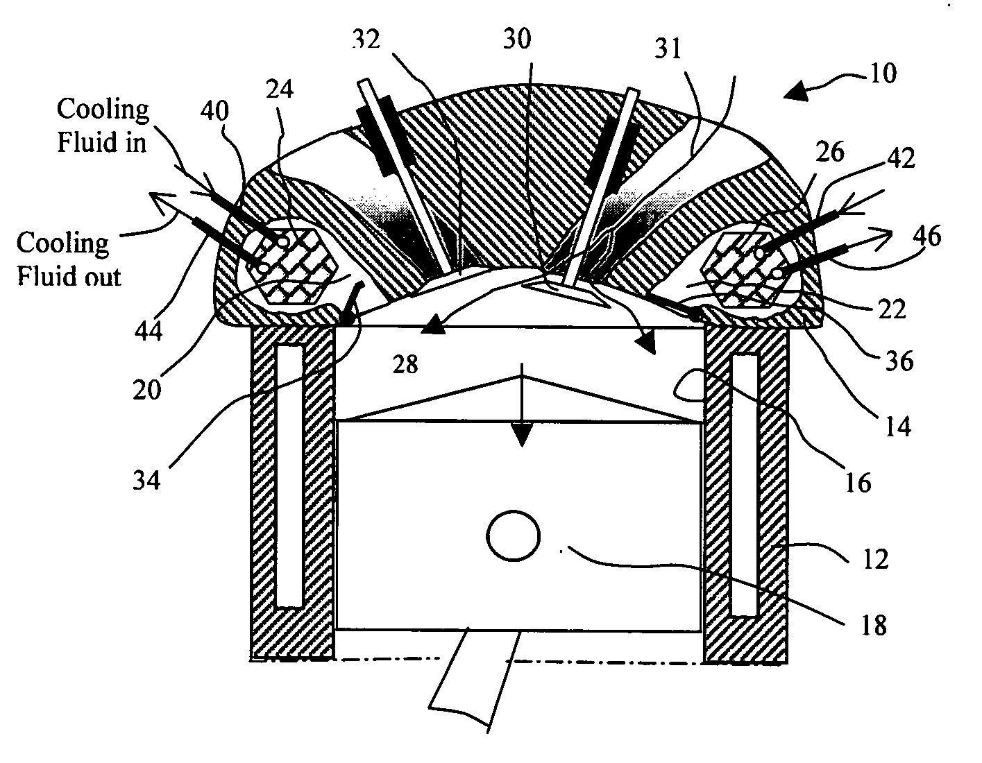
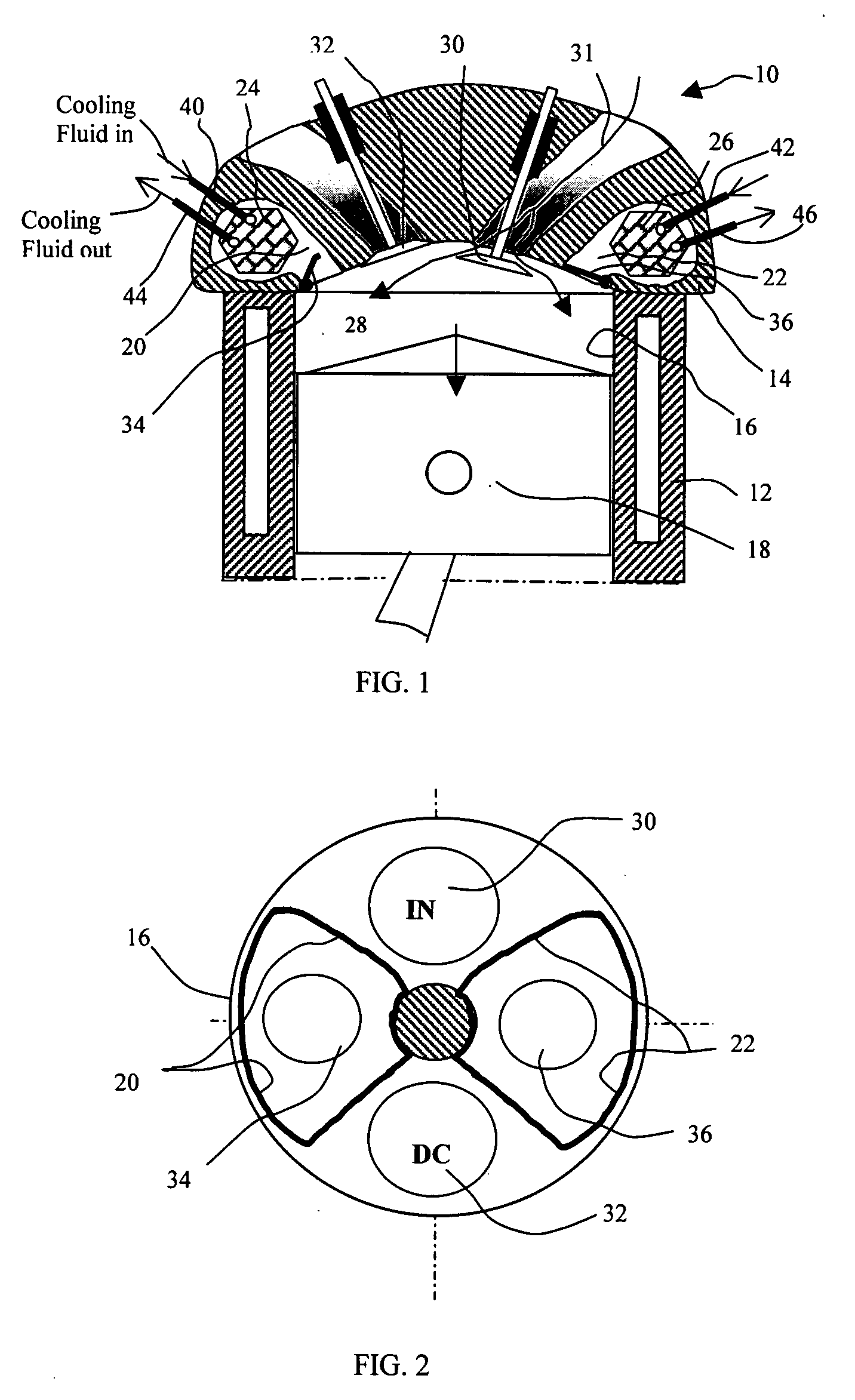
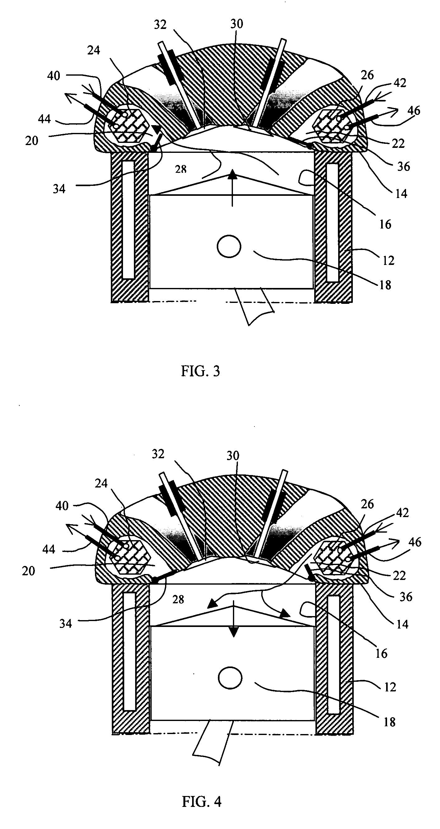
[0031]FIG. 1 illustrates a refrigerator 10 in accordance with the present invention, which includes a cylinder block 12 and a cylinder head 14. The cylinder block 12 contains at least a cylinder 16 and a piston 18 that is slidably disposed within the cylinder 16. Associated with each cylinder 16, the cylinder head 14 defines a first cooling chamber 20 and a second cooling chamber 22. Associated with said cooling chambers, a first heat exchanger unit 24 and a second heat exchanger unit 26 are disposed, respectively, within the cooling chambers 20 and 22. When the piston 18 reaches the top dead center (TC), cylinder space 28, as defined by the bottom face of the cylinder head 14, the top face of the piston 18, and the sidewall of the cylinder 16, may be minimized. The cylinder head is provided with an intake port and a discharge port, and the intake port has an intake valve 30, and the discharge port has a discharge valve 32. Additionally, the first cooling chamber 20 is provided with...


PUM


Abstract

This invention provides a refrigerator using a gaseous working fluid such as air and based upon the well-developed structure of reciprocating compressors or rotating engines. The invention combines the compression functionality of a compressor and the expansion functionality of a turbine in an air cycle machine into a single refrigeration unit having a simple mechanical structure, and provides a significantly increased heat removal time period before the expansion stroke to reduce the temperature of the working fluid under a substantially constant volume without increasing the number of strokes per discharge in a cycle. Moreover, the need of using a man-made chemical as the working fluid is eliminated. Said refrigerator system comprises at least a piston and cylinder assembly including a piston reciprocatingly mounted within the cylinder space, and at least two cooling chambers associated with said cylinder. Each said cooling chamber has therewithin a heat exchanger unit that facilitates heat transfer from the working fluid to a heat sink, a port leading to said cylinder space, and a cooling-chamber valve, said valve opening or closing said port to establish or block communication between said chamber and cylinder space. Said refrigerator is adapted to operate on a cycle having 4n essential strokes for a refrigerator utilizing intake and discharge strokes for respective intake and discharge purposes, or 2n essential strokes for a refrigerator utilizing a scavenging process for discharge and intake purposes, where n is the number of cooling chambers associated with each cylinder. For a refrigerator having intake and discharge strokes, each said cooling chamber has an associated compression stroke, an expansion stroke, and between said compression and expansion strokes a time period of 4(n-1) strokes available for heat transfer from the working fluid enclosed within the cooling chamber to the heat sink. For a refrigerator utilizing a scavenging process for discharge and intake, each said cooling chamber has an associated compression stroke, an expansion stroke, and between said compression and expansion strokes a time period of 2(n-1) strokes available for heat transfer from the working fluid enclosed within the cooling chamber to the heat sink. In both cases, during the time period of heat transfer between the enclosed working fluid and heat sink, said piston would provide strokes for the working fluid associated with another cooling chamber. Additionally, the structure of a rotating refrigerator based on the structure of a rotary engine is disclosed.

Description

CROSS REFERENCES TO RELATED APPLICATIONS [0001]This application is a continuation of provisional application 60 / 876,750 filed Dec. 22, 2006.FIELD OF INVENTION [0002]This invention relates to refrigerators, in particular related to refrigerators using a gas such as air as the working fluid.BACKGROUND [0003]A refrigerator is a system that lowers the temperature of a space or substance and then maintains that lower temperature. Currently, the predominant type of refrigeration system is the vapor-compression refrigeration system. Although other types of refrigeration systems such as absorption and jet ejector refrigeration systems have been developed, due to a lower coefficient of performance (COP), their uses are limited to certain applications where thermal energy is abundant. However, it is well known that many refrigerants currently used in vapor-compression refrigeration systems may have a negative environmental impact related to ozone layer depletion and global warming.[0004]A ref...

Claims


Application Information

Patent Timeline
Patent Type & Authority Applications(United States)
IPC IPC(8): F25D9/00
CPCF01C1/22Y02E10/46F25B9/004F04B39/064
Inventor CAO, YIDING
Owner CAO YIDING
Why Eureka
Try Eureka