Dynamic Microphone

Inactive Publication Date: 2012-06-07
AUDIO-TECHNICA
View PDF3 Cites 10 Cited by
  • Summary
  • Abstract
  • Description
  • Claims
  • Application Information

AI Technical Summary

Benefits of technology

[0018]Vibration of the microphone case is transmitted to the microphone unit case, causing vibration of magnetic circuit components substantially integrated with the microphone unit case. In response to the vibration of the magnetic circuit components, a movable portion including a diaphragm and a voice coil relatively moves due to an inertial force, generating vibration noise. The vibration of the microphone unit case is also transmitted to the vibration pickup, and the vibration pickup vibrates and outputs a signal corresponding to the received vibration. The vibration pick

Problems solved by technology

Vibration of the microphone case is transmitted to the microphone unit case, causing vibration of magnetic circuit components substantially integrated with the microphone unit case.
In re

Method used


Image

  • Dynamic Microphone
  • Dynamic Microphone
  • Dynamic Microphone

Examples


Embodiment Construction

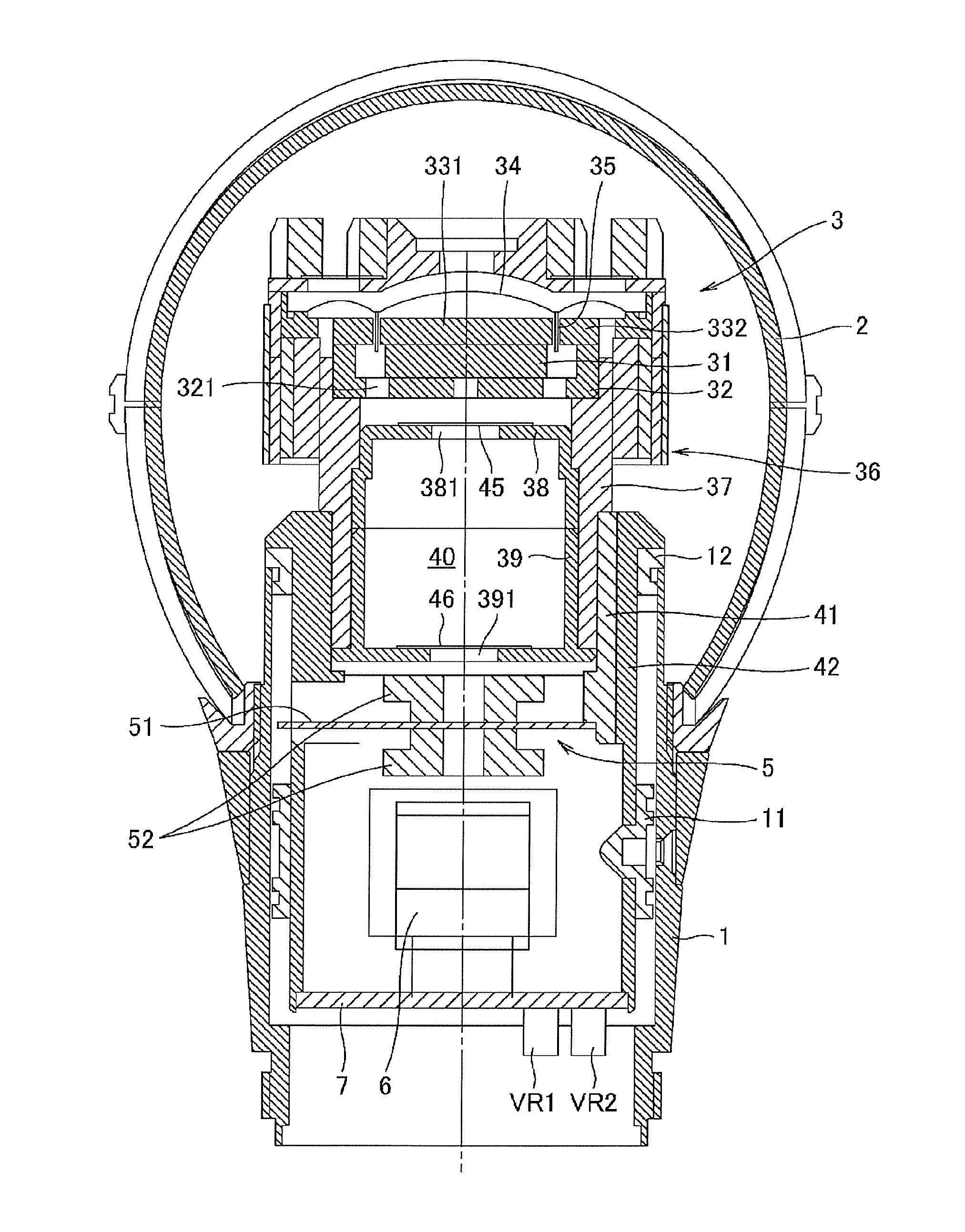
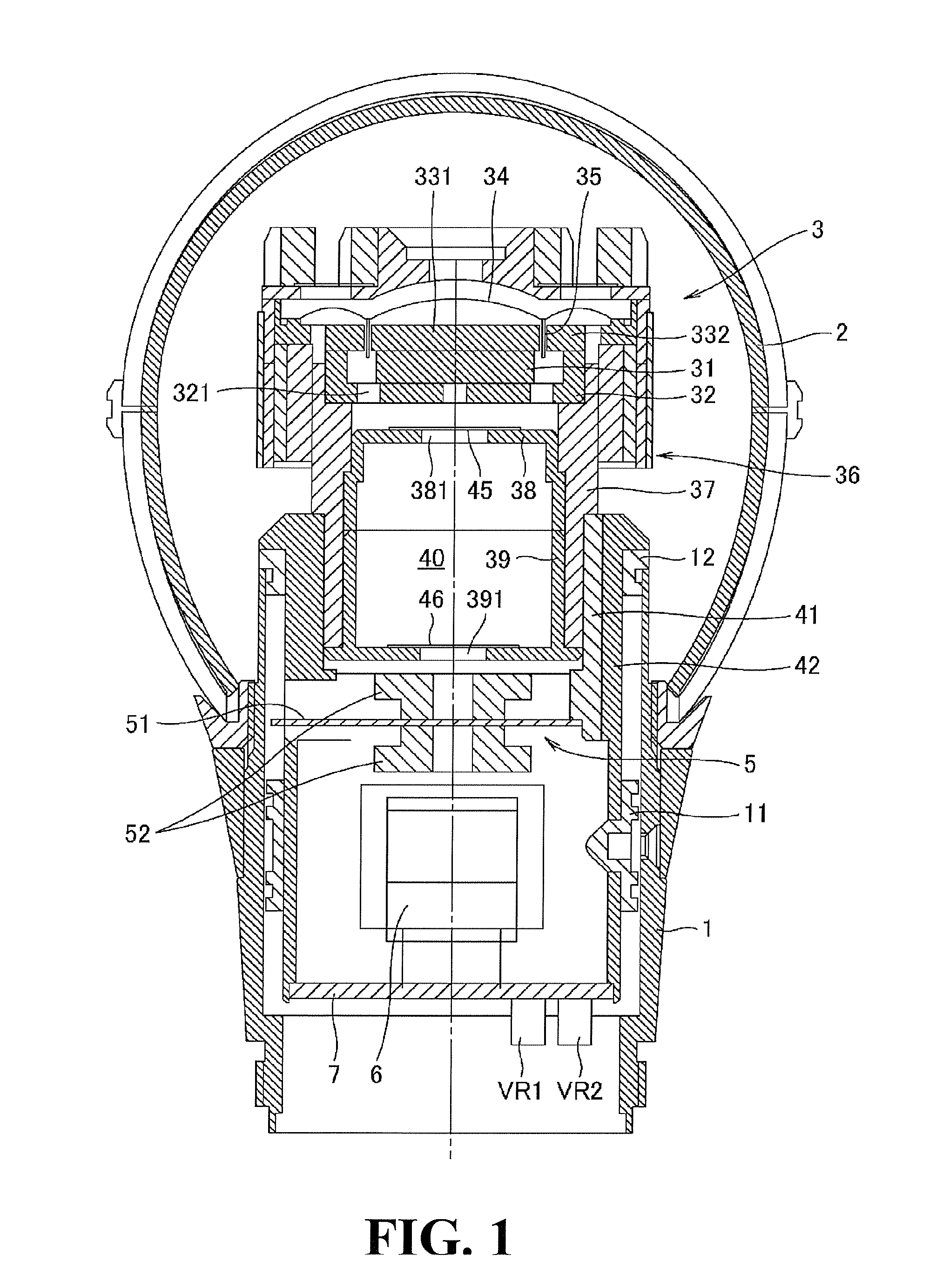
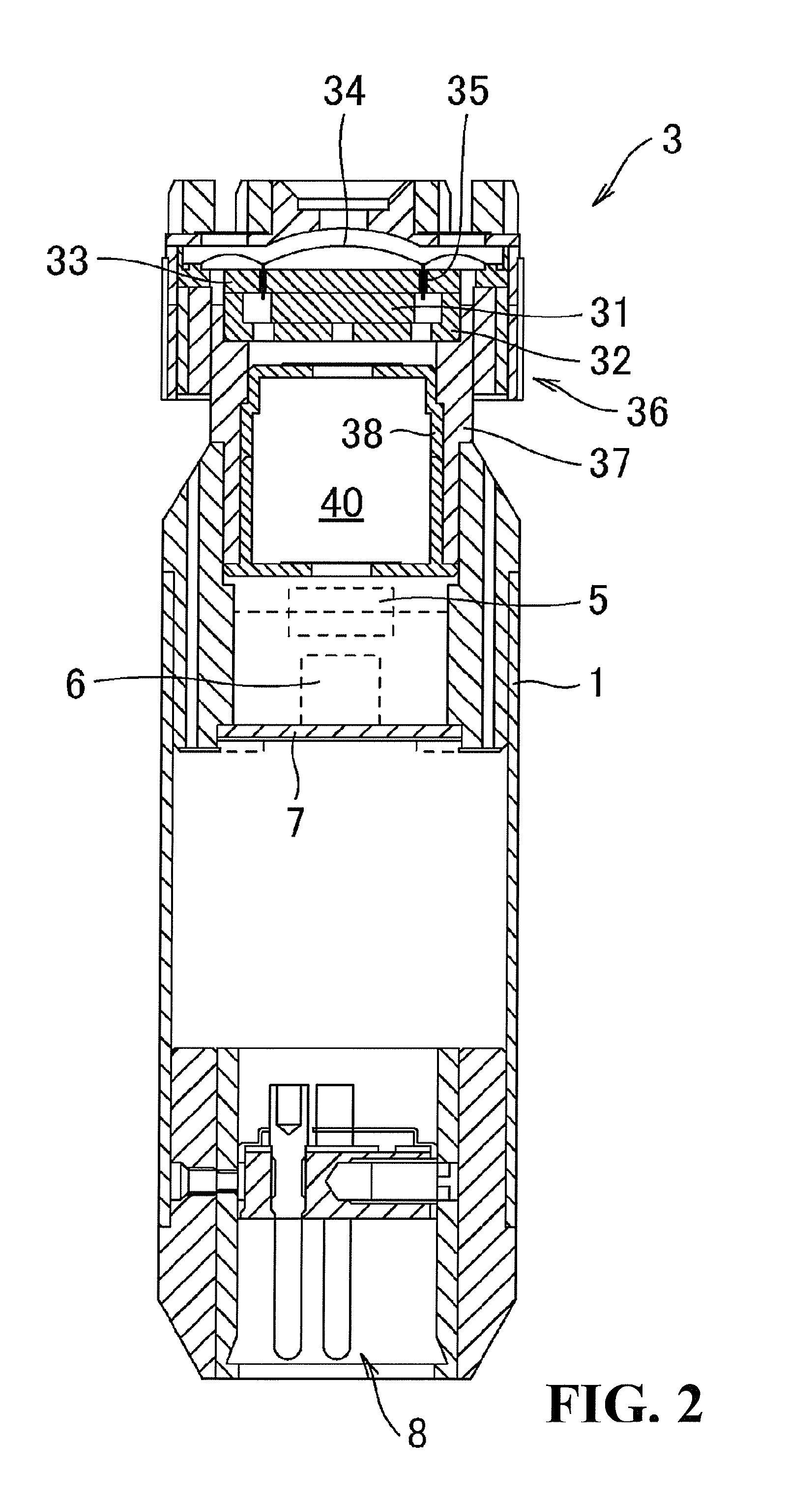
[0029]An embodiment of a dynamic microphone according to the present invention is described below with reference to the attached drawings.

[0030]With reference to FIGS. 1 and 2, a cylindrical microphone case 1 has an end (the upper end in the drawings) to which a dynamic microphone unit 3 and a vibration pickup 5 are fixed. The dynamic microphone unit 3 has a magnetic circuit including a flat-bottomed yoke 32, a circular magnet 31 fixed to the center on the inside bottom of the yoke 32, a pole piece 331 fixed to the top of the magnet 31, and an annular yoke 332 fixed to the upper end face of the yoke 32 around the pole piece 331.

[0031]The magnetic circuit has a cylindrical magnetic gap between the outer circumferential surface of the pole piece 331 and the inner circumferential surface of the yoke 332. A voice coil 35 is disposed in the magnetic gap while being fixed to a diaphragm 34. The diaphragm 34 includes a central dome having a partial spherical shape, and a sub-dome having an...


PUM


Abstract

A dynamic microphone includes a vibration pickup that detects vibration of a dynamic microphone unit, and outputs a signal for cancelling vibration noise; and a microphone case that supports the microphone unit and the vibration pickup, wherein the vibration pickup includes a laminated ceramic piezoelectric element that detects vibration of a microphone unit case and outputs a signal corresponding to the detected vibration, the laminated ceramic piezoelectric element has a capacitance that defines a resonance circuit in conjunction with an inductance of an inductor, the resonance circuit producing a response signal to acceleration corresponding to that of the vibration noise, and the resonance circuit is connected such that the response signal is output in an opposite direction to the vibration noise signal.

Description

BACKGROUND OF THE INVENTION[0001]1. Field of the Invention[0002]The present invention relates to a dynamic microphone having a structure and a circuit for reducing vibration noise, the circuit including a piezoelectric element having a certain capacitance as a vibration sensor for cancelling undesired vibration.[0003]2. Related Background Art[0004]A dynamic microphone includes a diaphragm and a voice coil fixed to the diaphragm, where the voice coil is disposed in a magnetic gap in a magnetic circuit including a magnet, a yoke, and a pole piece. The diaphragm vibrates upon receiving sound waves, and the voice coil also vibrates to traverse a magnetic flux in the magnetic gap. As a result, sound signals corresponding to the sound waves are output from the voice coil.[0005]A hand-held dynamic microphone tends to generate unpleasant noise due to vibration caused by rubbing a microphone case with a hand, gripping or placing the microphone, or any other handling. The vibration noise is r...

Claims


Application Information

Patent Timeline
IPC IPC(8): H04R1/02
CPCH04R3/04H04R2430/03H04R2410/05
Inventor AKINO, HIROSHIFURUYA, HIROAKISHIMURA, HARUHITOYOSHINO, SATOSHI
Owner AUDIO-TECHNICA
Why Eureka
Try Eureka