Microfluidic electrospray thruster

a microfluidic electrospray and thruster technology, applied in the field of thrusters, can solve the problems of prohibitive size, weight and complexity of spacecraft, limited exhaust velocity of such chemical rockets, and inability to use very small spacecraft or highly distributed propulsion on very large space structures, so as to reduce the viscosity of propellan

Inactive Publication Date: 2012-06-14
CALIFORNIA INST OF TECH
View PDF2 Cites 46 Cited by
  • Summary
  • Abstract
  • Description
  • Claims
  • Application Information

AI Technical Summary

Benefits of technology

[0027]In still yet another embodiment, the surface of the extractor electrode grid is grooved and/or roughened, and the grid is in thermal communication with a heating element capable of uniformly heating said extractor electrode grid to a temperature sufficient to melt the propellant and reduce the viscosi

Problems solved by technology

However, the exhaust velocity of such chemical rockets is limited by the inherent specific energy released by combustion, accordingly, chemical rockets burn up more propellant to effect an orbital maneuver than would other forms of propulsion.
Furthermore, the propellant reservoirs and feed systems for these types of chemical propulsion add prohibitively to the size, weight and complexity of the spacecraft, making then unusable for very small spacecraft or for highly distributed propulsion on very large space structures.
The drawback of the low thrust is low spacecraft acceleration because the mass of current electric power units is directly

Method used


Image

  • Microfluidic electrospray thruster
  • Microfluidic electrospray thruster
  • Microfluidic electrospray thruster

Examples


Embodiment Construction

[0054]The current invention is directed generally to an electrospray thruster, and, more particularly, to an electrospray thruster that increases thrust density of conventional electrospray thrusters by miniaturizing the individual components of the thruster thereby allowing for the increase in the number and density of thruster tips.

Conventional Electrospray Thrusters

[0055]Before turning to the design and implementation of the novel electrospray thrusters of the instant invention, the limitations of conventional thrusters need to be detailed. In particular, the problem being solved in the development of the novel miniaturized electrospray thrusters of the instant invention is the limited thrust density available from currently available conventional macroscale electrospray thrusters and their high mass and volume that are limiting these thrusters' applicability.

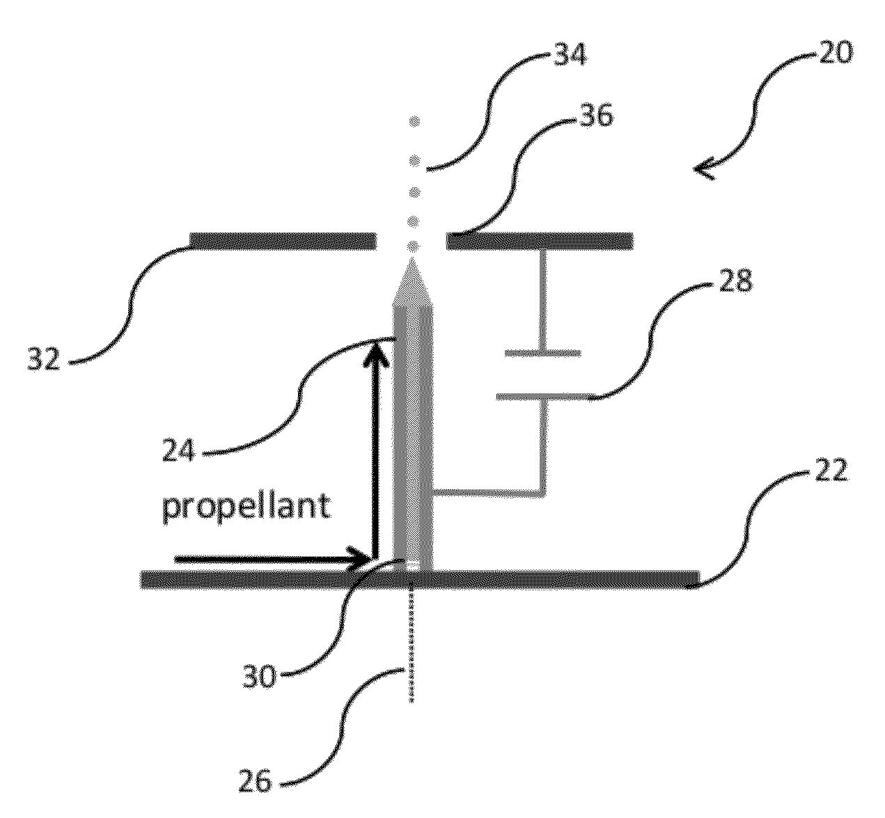
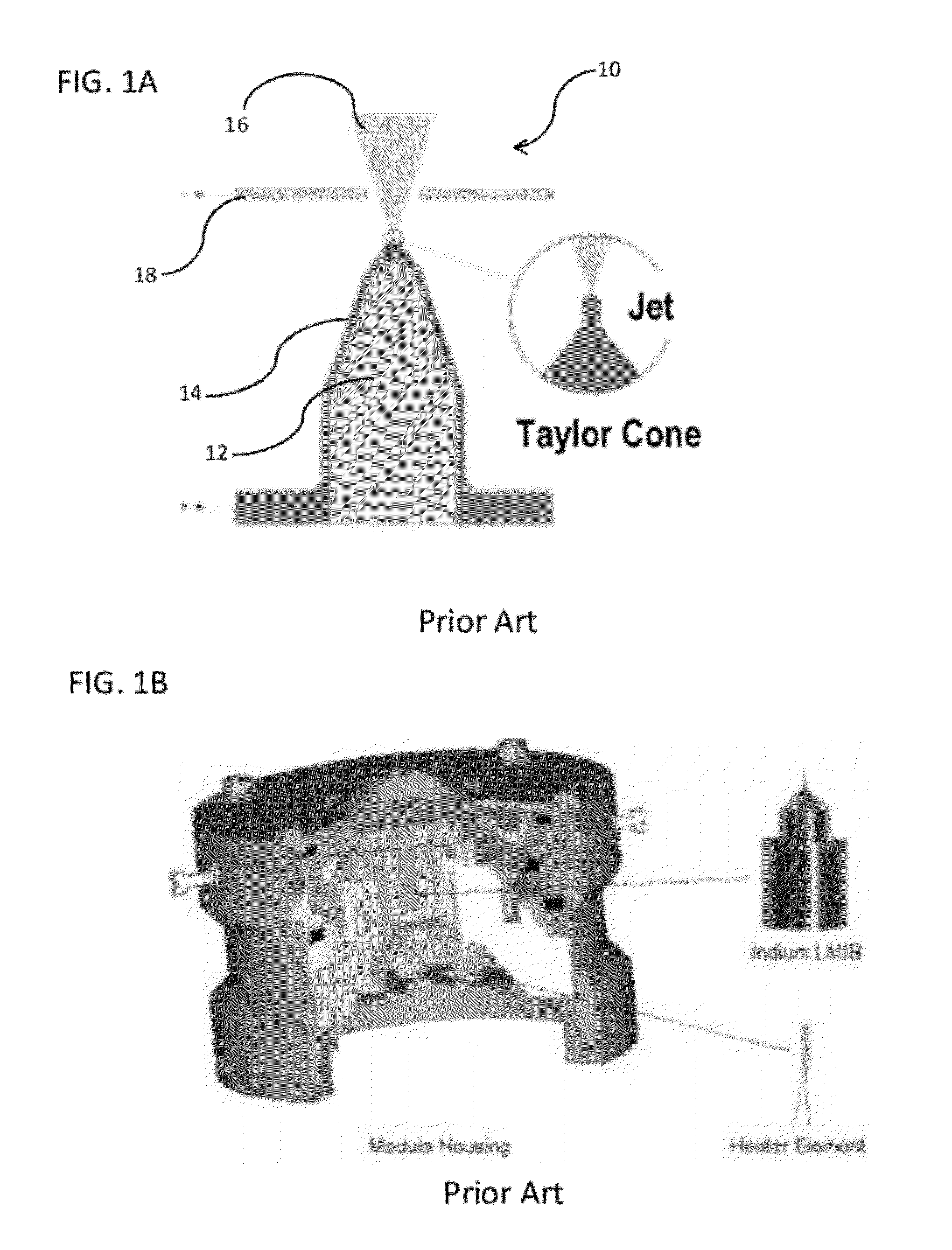
[0056]As shown in FIG. 1A, a conventional electrospray thruster (10) feeds propellant (12) to the tip of an externally wet...


PUM

PropertyMeasurementUnit
Temperatureaaaaaaaaaa
Lengthaaaaaaaaaa

Abstract

An electrospray thruster and methods of manufacturing such thrusters are provided. The micro-electrospray thruster increases the thrust density of conventional electrospray thrusters by miniaturizing the individual components of the thruster thereby allowing for the increase in the number and density of the charged particle emitters.

Description

CROSS-REFERENCE TO RELATED APPLICATION[0001]The current application claims priority to U.S. Provisional Application No. 61 / 288,760, filed Dec. 21, 2009, the disclosure of which is incorporated herein by reference.STATEMENT OF FEDERAL FUNDING[0002]The federal government has rights to the current invention pursuant to funding provided in accordance with Grant Nos. NMO-715914 and NMO-716114 issued by the Defense Advanced Research Projects Agency, and a NASA contract.FIELD OF THE INVENTION[0003]The present invention relates to a thruster for the propulsion of an object in space; and in particular, the invention relates to a microfluidic electrospray thruster.BACKGROUND OF THE INVENTION[0004]There is a rapidly growing commercial demand for small satellites, and, more particularly, for satellite instruments that demand precision control of position and orientation on small and large spacecraft. However, there is concomitant need for a significant reduction in the cost and complexity of th...

Claims


Application Information

Patent Timeline
IPC IPC(8): F03H1/00C23C8/02C25D13/02C25D13/20C25D5/34B05D3/00C23C14/34
CPCB64G1/405F03H1/0031F03H1/0012
Inventor MARRESE-READING, COLLEEN M.MUELLER, JUERGENWEST, WILLIAM C.
Owner CALIFORNIA INST OF TECH
Why Eureka
Try Eureka