Bonding structure and bonding method of heat diffusion member, and cooling unit using the same
- Summary
- Abstract
- Description
- Claims
- Application Information
AI Technical Summary
Benefits of technology
Problems solved by technology
Method used
Image

Examples
first embodiment
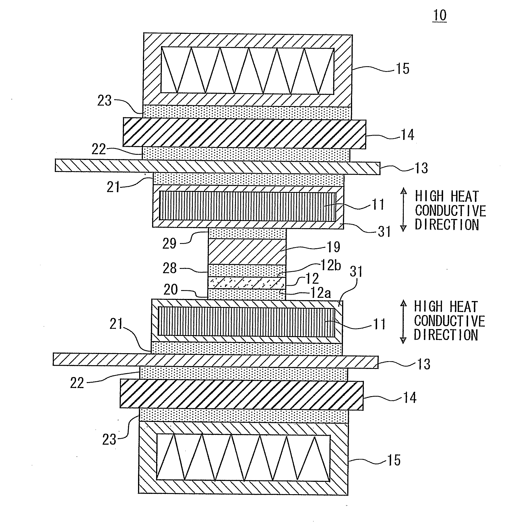
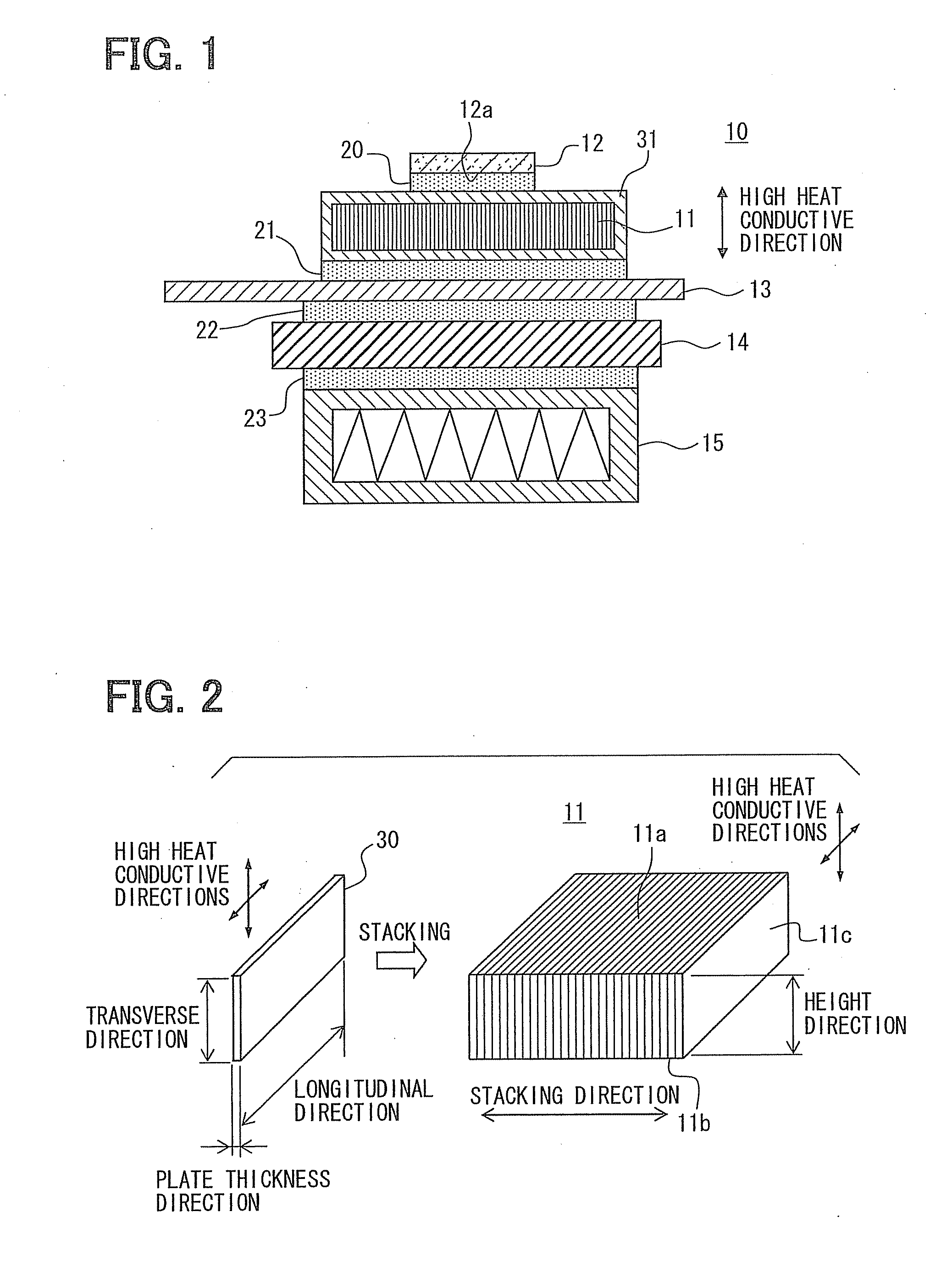
[0032]Hereinafter, a cooling unit 10 having a heat source 12 and a heat diffusion member 11, a bonding structure of the heat diffusion member 11, and a bonding method of the heat diffusion member 11 according to the first embodiment will be described with reference to FIGS. 1 through 3. Hereinafter, the cooling unit 10 will be also referred to as a heat source module 10.
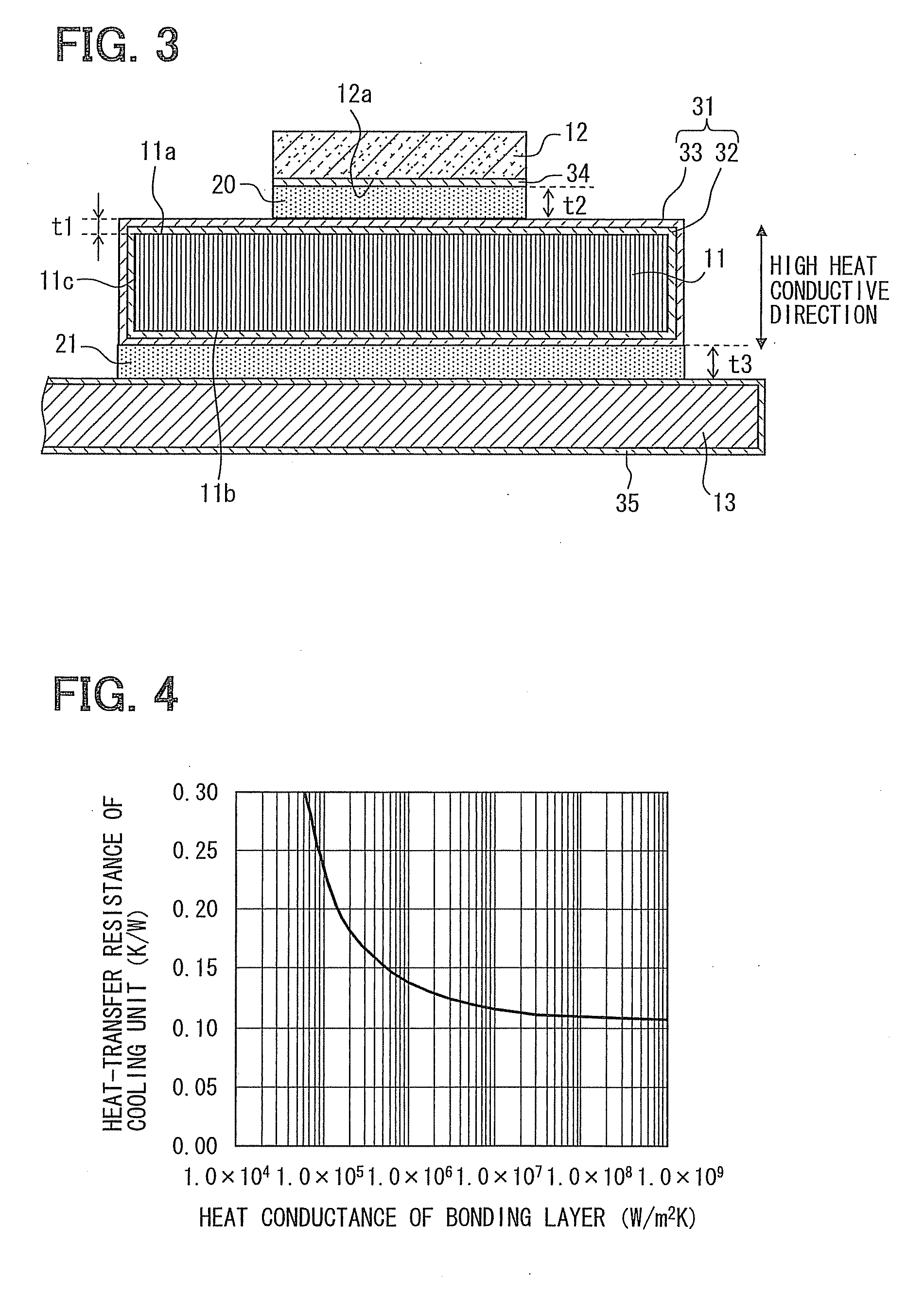
[0033]As shown in FIG. 1, the heat source module 10 includes the heat diffusion member 11, the heat source 12, a metal member 13, an electric insulating layer 14, and a cooler 15. The heat diffusion member 11 has a metal thin film 31 on its surface.
[0034]The heat source 12 is bonded to a surface of the heat diffusion member 11 through a bonding member 20. The metal member 13 is bonded to an opposite surface of the heat diffusion member 11 through a bonding member 21.
[0035]The electric insulating layer 14 is bonded to a surface of the metal member 13 through a bonding member 22 on an opposite side to the heat diffusio...
second embodiment
[0108]A second embodiment will be described with reference to FIGS. 8 and 9. Hereinafter, a structure different from the heat source module 10 of the first embodiment will be mainly described.
[0109]In the first embodiment, the heat source module 10 has only one heat diffusion member 11 between the heat source 12 and the metal member 13. In the present embodiment, on the other hand, the heat source module 10 has two heat diffusion members, such as a first heat diffusion member 16 and a second heat diffusion member 17, between the heat source 12 and the metal member 13. In other words, the heat diffusion member 11 is provided by the first heat diffusion member 16 and the second heat diffusion member 17.
[0110]The heat diffusion members 16, 17 are layered in the thickness direction thereof, that is, in the up and down direction of FIG. 8. The first heat diffusion member 16 and the second heat diffusion member 17 have substantially the same structure as the heat diffusion member 11 of th...
third embodiment
[0128]A third embodiment will be described with reference to FIG. 10. Hereinafter, a structure different from the above described embodiments will be mainly described.
[0129]In the above described embodiments, the heat diffusion member 11 is disposed between the heat source 12 and the metal member 13. In the present embodiment, the heat diffusion member 11 is disposed between the metal member 13 and the electric insulating layer 14, as shown in FIG. 10.
[0130]As shown in FIG. 10, the heat source module 10 has the similar components to the heat source module 10 of the first embodiment, but the metal member 13 and the electric insulating layer 14 are arranged adjacent to the heat diffusion member 11. Thus, the metal member 13 and the electric insulating layer 14 correspond to the second member.
[0131]The bonding member 21 disposed between the metal member 13 and the heat diffusion member 11 is same as the bonding member 21 of the first embodiment. A bonding member 25 disposed between the...
PUM
| Property | Measurement | Unit |
|---|---|---|
| Thickness | aaaaa | aaaaa |
| Electrical conductivity | aaaaa | aaaaa |
| Structure | aaaaa | aaaaa |
Abstract
Description
Claims
Application Information
 - R&D
- Intellectual Property
- Life Sciences
- Materials
- Tech Scout
- Unparalleled Data Quality
- Higher Quality Content
- 60% Fewer Hallucinations
Browse by: Latest US Patents, China's latest patents, Technical Efficacy Thesaurus, Application Domain, Technology Topic, Popular Technical Reports.
© 2025 PatSnap. All rights reserved.Legal|Privacy policy|Modern Slavery Act Transparency Statement|Sitemap|About US| Contact US: help@patsnap.com