Membrane bioreactor (MBR) and moving bed bioreactor (MBBR) configurations for wastewater treatment

a bioreactor and moving bed technology, applied in the field of wastewater treatment systems, can solve the problems of large amount of sludge, large area of land, and time-consuming asp systems

Active Publication Date: 2012-06-21
XEROX CORP
View PDF0 Cites 17 Cited by
  • Summary
  • Abstract
  • Description
  • Claims
  • Application Information

AI Technical Summary

Benefits of technology

[0030]The water treatment system and method incorporates the use of a hydrodynamic separator to remove most of the total suspended solids (TSS) in source water being treated to thereby lighten the load on membrane filtration in the water treatment system and lower energy costs.

Problems solved by technology

The ASP system is, however, quite time consuming, and requires large areas of land, and produces large amounts of sludge.
Membrane fouling is a serious problem affecting the system performance; as it leads to significant increase in hydraulic resistance, manifested as permeate flux decline or trans-membrane pressure (TMP) increase.
Thus MBR based processes involve high capital costs due to the expensive membranes, and high operation and maintenance costs due to increased energy for the aeration, trans-membrane pressure, and frequent back-flushing and / or other cleaning of the membranes to maintain their usefulness.

Method used


Image

  • Membrane bioreactor (MBR) and moving bed bioreactor (MBBR) configurations for wastewater treatment
  • Membrane bioreactor (MBR) and moving bed bioreactor (MBBR) configurations for wastewater treatment
  • Membrane bioreactor (MBR) and moving bed bioreactor (MBBR) configurations for wastewater treatment

Examples


Embodiment Construction

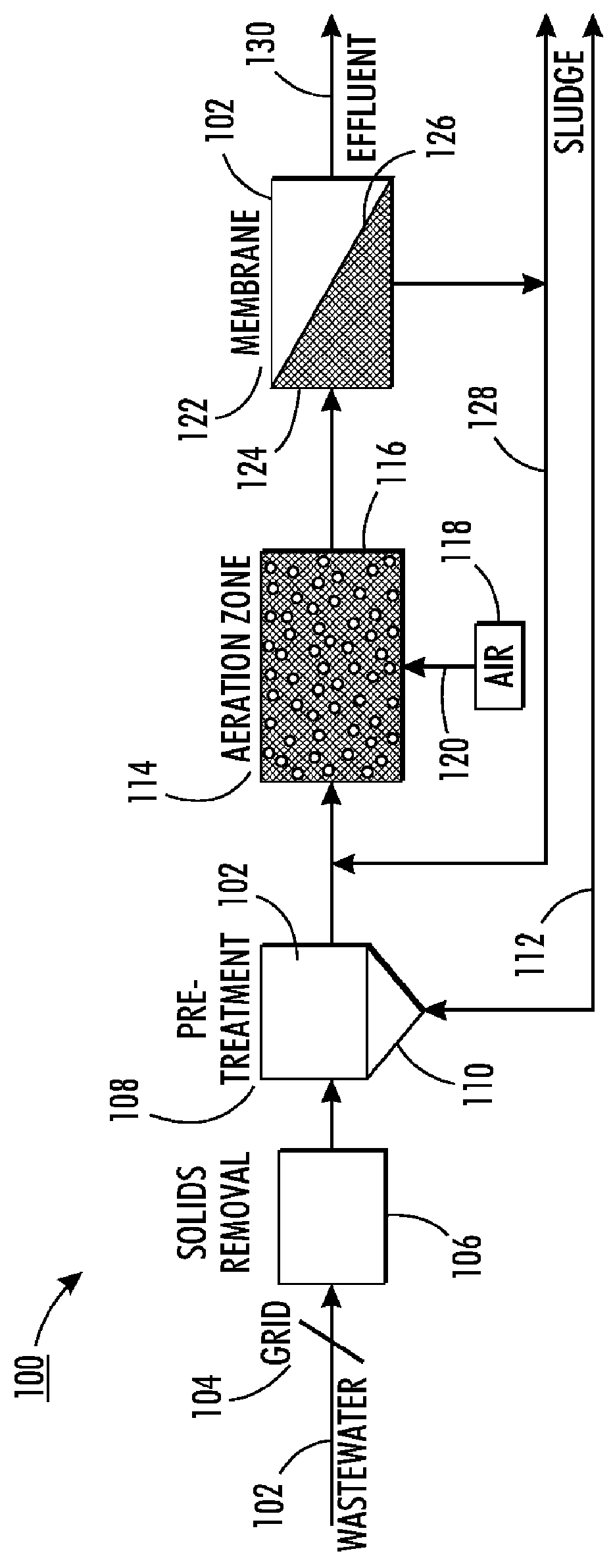
[0048]FIG. 1 illustrates a membrane bioreactor (MBR) source water treatment process system 100. The source water may, as mentioned, be water from a number of different locations and may contain algae and / or active sludge bacteria floc, among other elements. Source water containing active sludge biological floc should behave very similarly to algae-laden water, both having similar specific gravity. Such floc is often formed on filamentous bacteria, and floc size will decrease with increasing sludge age. Active sludge bacteria floc also posses the same risk of biofilm accumulation as that of water carrying algae, and range in size between 10-200 microns. Biological floc can be found in concentrations of 500-10000 mg / l (TSS). Granular sludge up to 1 mm can be formed under certain conditions and selected bacteria strains.

[0049]In system 100, source water 102 is supplied through a grid or screen 104. A solid removal module 106 processes the source water 102 in a known manner to remove la...


PUM

PropertyMeasurementUnit
sizesaaaaaaaaaa
sizeaaaaaaaaaa
concentrationsaaaaaaaaaa

Abstract

The water treatment system and method incorporating the use of a hydrodynamic separator to remove most of the total suspended solids (TSS) in source water being treated to thereby lighten the load on membrane filtration in the water treatment system and lower energy costs.

Description

INCORPORATION BY REFERENCE[0001]The following co-pending and commonly assigned applications, the disclosures of each being totally incorporated herein by reference, are mentioned:[0002]U.S. Published Application No. 2009 / 0050538, entitled, “Serpentine Structures for Continuous Flow Particle Separations”, by Lean et al.;[0003]U.S. Published Application No. 2008 / 0128331, entitled, “Particle Separation and Concentration System”, by Lean et al.;[0004]U.S. Published Application No. 2008 / 0230458, entitled, “Vortex Structure for High Throughput Continuous Flow Separation”, by Lean et al.;[0005]U.S. Published Application No. 2009 / 0114601, entitled, “Device and Method for Dynamic Processing in Water Purification”, by Lean et al.;[0006]U.S. Published Application No. 2009 / 0114607, entitled, “Fluidic Device and Method for Separation of Neutrally Buoyant Particles”, by Lean et al.;[0007]U.S. Published Application No. 2010 / 140092, entitled, “Flow De-Ionization Using Independently Controlled Volta...

Claims


Application Information

Patent Timeline
Patent Type & Authority Applications(United States)
IPC IPC(8): C02F3/02
CPCC02F3/1268C02F1/385C02F3/085Y02W10/10C02F1/44B01D61/00
Inventor LEAN, MENG H.ZUBACK, JOEPAREKH, NITINCHANG, NORINE E.HSIEH, HUANGPIN BENMELDE, KAI
Owner XEROX CORP
Why Eureka
Try Eureka