
Passively Cooled Lightweight Thermoelectric Generator System

a generator system and lightweight technology, applied in the direction of machines/engines, mechanical energy handling, mechanical equipment, etc., can solve the problems of many people without access to electrical power, many people the developed electrical grid may lose electricity access, so as to improve thermal linkage, reduce thermal conductivity, and improve thermal conductivity

Active Publication Date: 2012-06-21
DARK ORANGE DESIGN INC
View PDF3 Cites 10 Cited by
  • Summary
  • Abstract
  • Description
  • Claims
  • Application Information

AI Technical Summary

Benefits of technology

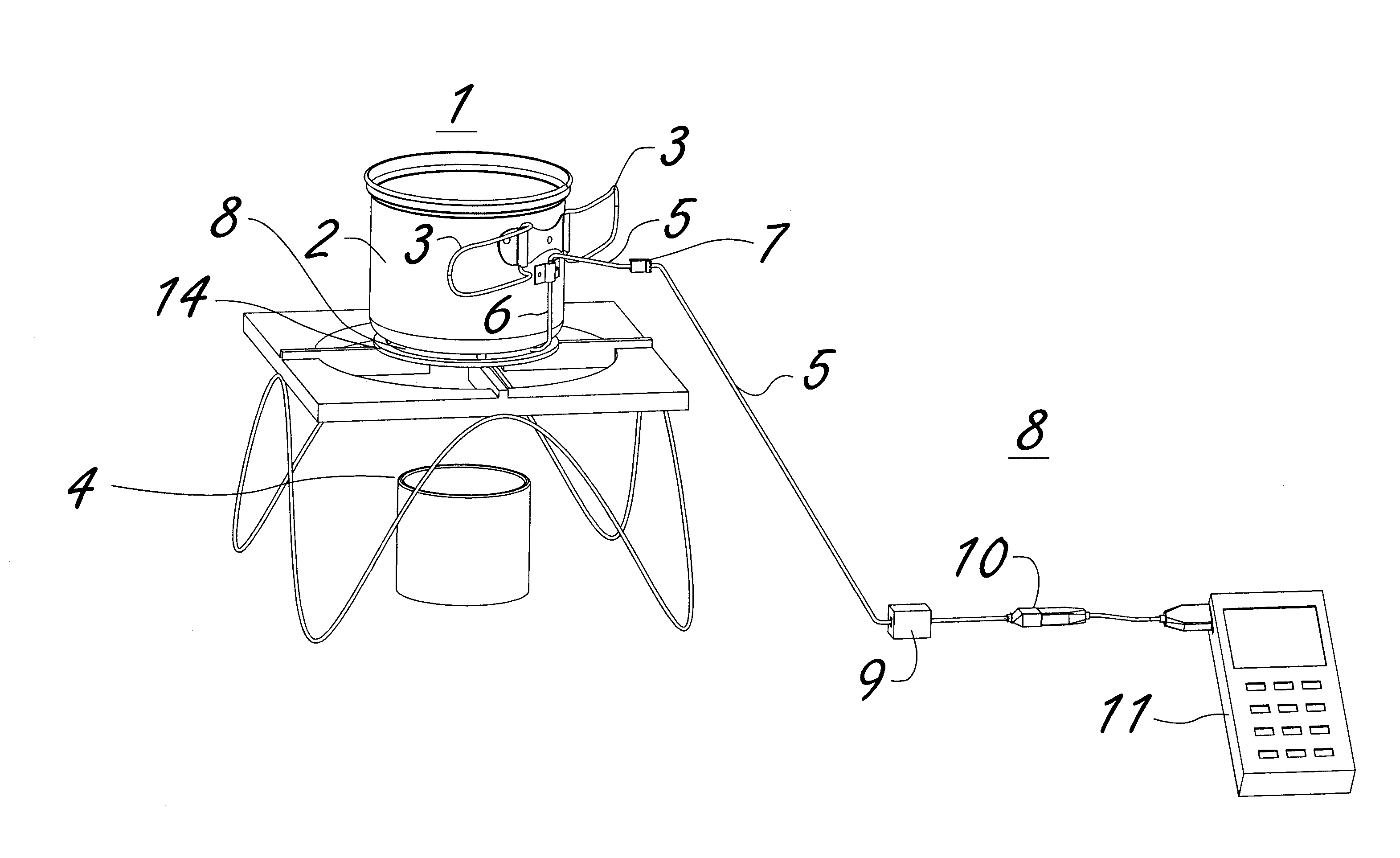
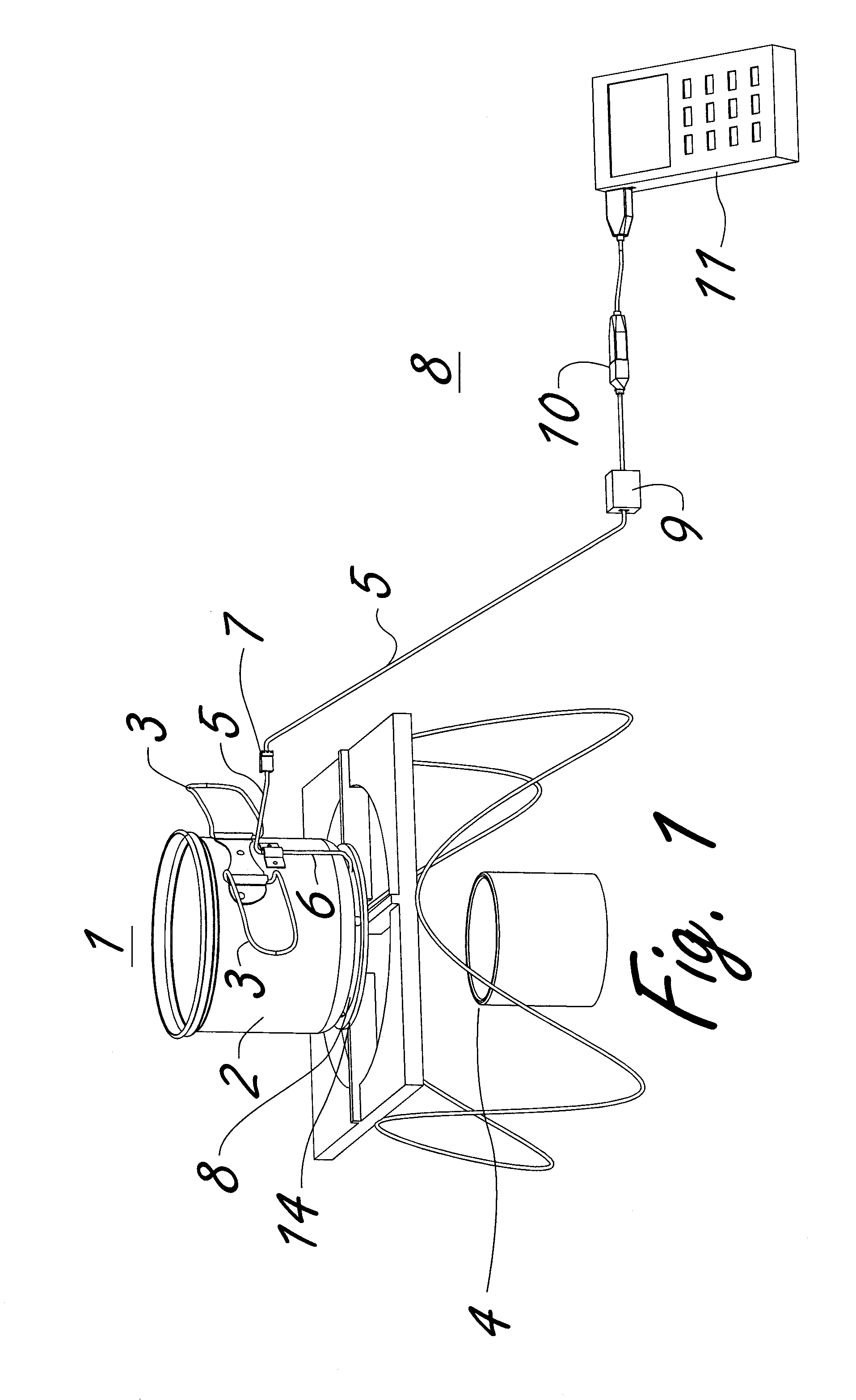
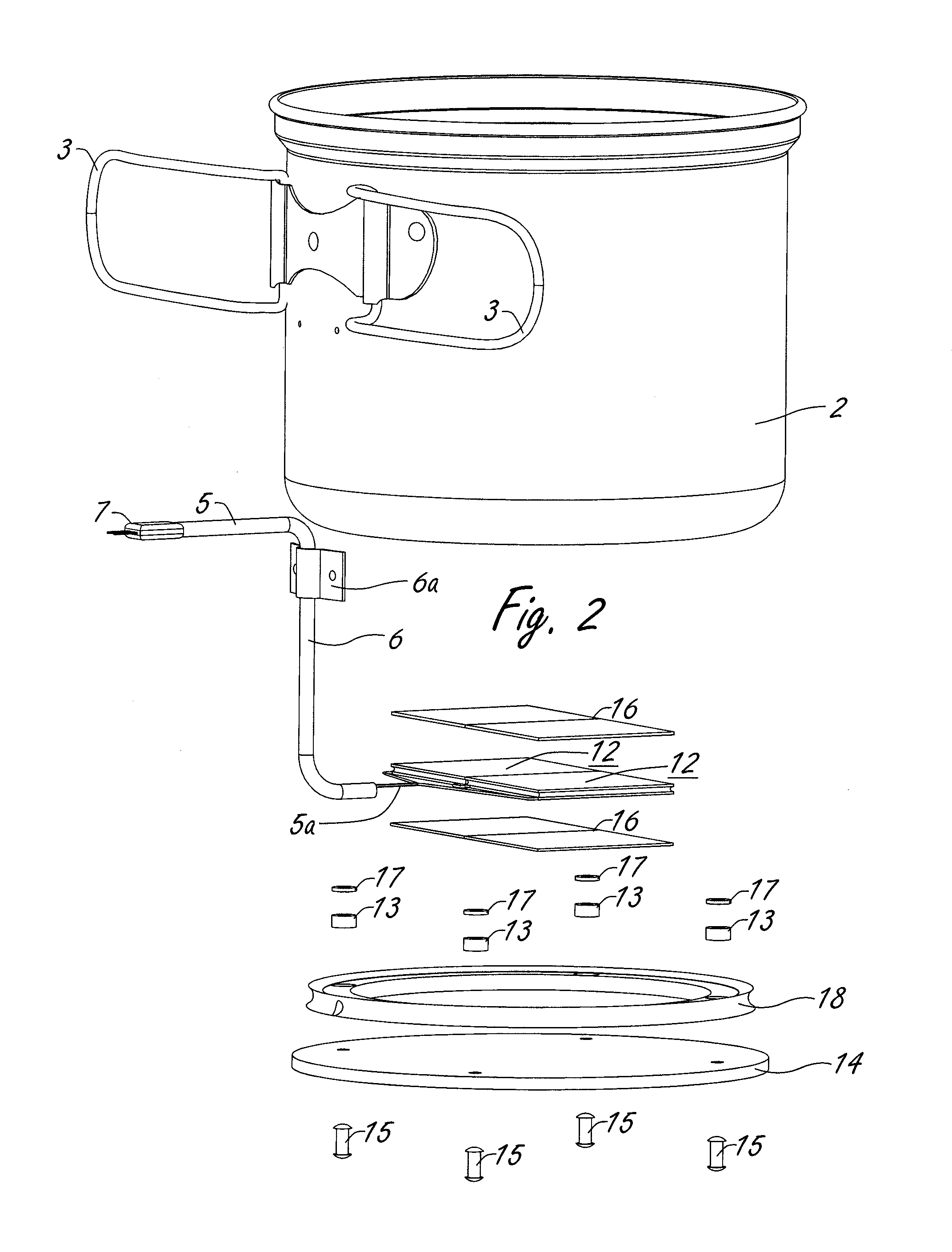
[0005]According to one embodiment, a portable device for generating electrical power comprises a vessel configured to retain a phase change material. The vessel has a bottom portion and a side wall. The device includes a thermoelectric generator module which has a top side and a bottom side, and a gasket having an opening. A bottom plate is provided, and a material of the bottom plate has a higher thermal conductivity than a material of the gasket. The device includes a DC to DC voltage regulator, and a temperature resistant wire having first and second ends. The wire is at least partially enclosed within a temperature resistant conduit, and its first end is coupled to the module. A first thermal interface enhancer is adjacent the top side of the module, and a second thermal interface enhancer is adjacent the bottom side of the module. The device further includes a hollow spacer, and a thermal interface inhibitor that comprises a material having a lower thermal conductivity than the material of the bottom plate. The bottom plate is secured to the bottom portion of the vessel with a fastener such that an area is formed between them. The gasket is secured to the bottom plate within the area. The spacer is configured around the fastener, and the thermoelectric generator module is enclosed within the opening of the gasket. The module is positioned such that the module top side is relatively near to the bottom portion of the vessel and the module bottom side is relatively distant to the bottom portion of the vessel. The thermal interface inhibitor is secured adjacent the bottom portion above the spacer, and is configured to aid in the maintenance of a temperature differential between the vessel and the bottom plate when the bottom plate is heated. The first thermal interface enhancer is configured to improve thermal linkage between the bottom portion of the vessel and the top side of the module, and the second thermal interface enhancer is configured to improve thermal linkage between the bottom plate and the bottom side of the module.
[0006]According to another embodiment, a system for generating electrical power comprises a vessel configured to retain a phase change material. The vessel has a bottom portion and a sidewall. A thermoelectric generator module of the system has a top side and a bottom side. The system includes a bottom plate spaced apart from the vessel, forming an area. An interchangeable DC to DC voltage regulator is included, and a temperature resistant wire that is coupled to the thermoelectric generator module. A first thermal interface enhancer is adjacent the top side of the module, and a second thermal interface enhancer is adjacent the bottom side of the module. At least one of the first and second thermal interface enhancers comprise polyalphaolefin grease. A thermal interface inhibitor comprises a material having a lower thermal conductivity than a material comprising the bottom plate. The first thermal interface enhancer is configured to decrease a thermal impedance between the bottom portion of the vessel and the top side of the module, and the second thermal interface enhancer is configured to decrease a thermal impedance between the bottom plate and the bottom side of the module. The thermal interface inhibitor is configured to aid in the maintenance of a localized temperature differential between the vessel and the bottom plate when the bottom plate is heated.
[0007]According to yet another embodiment, a portable device for generating electrical power comprises a vessel comprising aluminum. The vessel is configured to retain a phase change material, and has a bottom portion and a side wall. A gasket having an opening is included, along with a bottom plate that comprises a material having a higher thermal conductivity than a material of the gasket. A temperature resistant wire has a first end and a second end. The first end is coupled to the thermoelectric generator module. A thermal interface enhancer is adjacent one of the top side of the module and the bottom side of the module. A thermal interface inhibitor is included, and comprises a material having a lower thermal conductivity than the material comprising the bottom plate. A hollow spacer has a height equal to or greater than the height of the module. The bottom plate is secured to the bottom portion of the vessel with a fastener such that an area is formed between them. The gasket is secured to the bottom plate within the area with a fastener, and the spacer is configured around the fastener. The thermoelectric generator module is enclosed within the opening of the gasket. The module is positioned such that the module top side is relatively near to the bottom portion of the vessel and the module bottom side is relatively distant to the bottom portion of the vessel. The thermal interface inhibitor is configured to aid in the maintenance of a temperature differential between the vessel and the bottom plate when the bottom plate is heated.

Problems solved by technology

However, billions of people use biomass such as wood and other plant matter as a primary energy source, and lack access to any form of electrical power with which they can power and charge electrical devices.
Indeed, a reliable power source is presently available only to roughly half of the total global population that resides within an established electrical grid, and even industrialized nations with a well-developed electrical grid may lose access to electricity during power outages.
Moreover, many people lack access to electrical power when enjoying outdoor activities, or when traveling through remote areas.
However, solar chargers are often fragile and costly, and may be unable to generate power in scenarios where sufficient sunlight is not available, such as when indoors, at night, and in inclement weather.
However, batteries add significant weight to any venture, generally have a fairly limited shelf-life, and their performance may suffer in cold and hot weather.
However, portable and reliable thermoelectric power generators are noticeably absent from the marketplace.

Method used


Image

  • Passively Cooled Lightweight Thermoelectric Generator System
  • Passively Cooled Lightweight Thermoelectric Generator System
  • Passively Cooled Lightweight Thermoelectric Generator System

Examples


Embodiment Construction

[0012]The present invention utilizes the thermoelectric effect to generate electricity. More specifically, the temperature difference imposed across a thermoelectric element creates a voltage due to the differences in diffusivity and phonon drag imposed upon the n-type and p-type carriers within the thermoelectric element. Under the second law of thermodynamics, from statistical mechanics interpretation, the thermoelectric power of a material can also be defined as the entropy per charge carrier. The present invention harnesses the entropy created by the temperature differential imposed by the system, and transforms this entropy (heat) into electrical power.

[0013]Thomas J. Seebeck discovered thermoelectric power in 1821, and the conversion of temperature differences directly into electricity is appropriately known as the Seebeck effect. To realize a true thermoelectric device, both n-type and p-type materials are electrically coupled to complete a circuit. Jean-Charles Peltier disco...


PUM


Abstract

A portable device for generating electrical power comprises a vessel and a thermoelectric generator module. A gasket having an opening is included, along with a bottom plate that comprises a material having a higher a higher thermal conductivity than a material comprising the gasket. A thermal interface enhancer is adjacent one of the top side of the module and the bottom side of the module. A thermal interface inhibitor is also included. The bottom plate is secured to the bottom portion of the vessel with a fastener such that an area is formed between them. The gasket is secured to the bottom plate within the area, and the spacer is configured around the fastener. The thermal interface inhibitor is configured to aid in the maintenance of a temperature differential between the vessel and the bottom plate when the bottom plate is heated.

Description

CROSS-REFERENCE TO RELATED APPLICATIONS[0001]This application claims priority to U.S. Provisional Patent Application Ser. No.: 61 / 425,699 filed Dec. 21, 2010, the disclosure of which is incorporated herein by reference.BACKGROUND OF THE INVENTION[0002]Portable electronic devices such as phones, radios, MP3 players, GPS units, et cetera, have become ubiquitous in societies across the globe. However, billions of people use biomass such as wood and other plant matter as a primary energy source, and lack access to any form of electrical power with which they can power and charge electrical devices. Indeed, a reliable power source is presently available only to roughly half of the total global population that resides within an established electrical grid, and even industrialized nations with a well-developed electrical grid may lose access to electricity during power outages. Moreover, many people lack access to electrical power when enjoying outdoor activities, or when traveling through...

Claims


Application Information

Patent Timeline
Patent Type & Authority Applications(United States)
IPC IPC(8): F02B63/04
CPCF01N5/025Y02T10/166H01L35/30Y02T10/12H10N10/13
Inventor TOLEDO, DAVIDSLUSSER, PAUL
Owner DARK ORANGE DESIGN INC
Learn More