
Single Wall Carbon Nanotubes By Atmospheric Chemical Vapor Deposition

a carbon nanotube and chemical vapor deposition technology, applied in the field of systems and methods for producing carbon nanotubes, can solve the problems of high scale-up production costs of swnts, high cost of mwnts, and high cost of hipco nanotubes

Inactive Publication Date: 2012-06-21
NEW JERSEY INSTITUTE OF TECHNOLOGY
View PDF3 Cites 10 Cited by
  • Summary
  • Abstract
  • Description
  • Claims
  • Application Information

AI Technical Summary

Benefits of technology

[0012]The present disclosure provides for advantageous systems and methods for producing carbon nanotubes, and, more particularly, to systems and methods for producing single wall carbon nanotubes (SWNTs) by chemical vapor deposition (CVD) using a carbon source in the presence of a catalyst. I

Problems solved by technology

However, one limiting factor for SWNTs is their comparatively higher cost than MWNTs.
Generally, because of the high growth temperature and the concomitant formation of a large fraction of disordered carbon, the scaled-up production costs by these methods are high.
For example, using the HiPCO method, SWNT with a purity of about 75-80% have been achieved, but because of the high temperature and pressure used, and the need to remove relatively large amounts of catalyst, HiPCO nanotubes remain expensive.
SWNTs produced by the CoMoCat process generally use lower pressures than the HiPCO method, but typically the use of a silica support, which generally is difficult to dissolve, makes purification nearly as expensive as for the HiPCO method.
Thus, the production of SWNTs for bulk applications remains challenging and expensive due to various factors.
For example, in regards to the HiPCO process, the high pressure processing is costly, and the removal of catalysts and amorphous carbon is expensive and inefficient.
In addition, in regards to the CoMoCat process, for example, the removal of catalyst and support is expensive and inefficient.

Method used


Image

  • Single Wall Carbon Nanotubes By Atmospheric Chemical Vapor Deposition
  • Single Wall Carbon Nanotubes By Atmospheric Chemical Vapor Deposition
  • Single Wall Carbon Nanotubes By Atmospheric Chemical Vapor Deposition

Examples


example 1

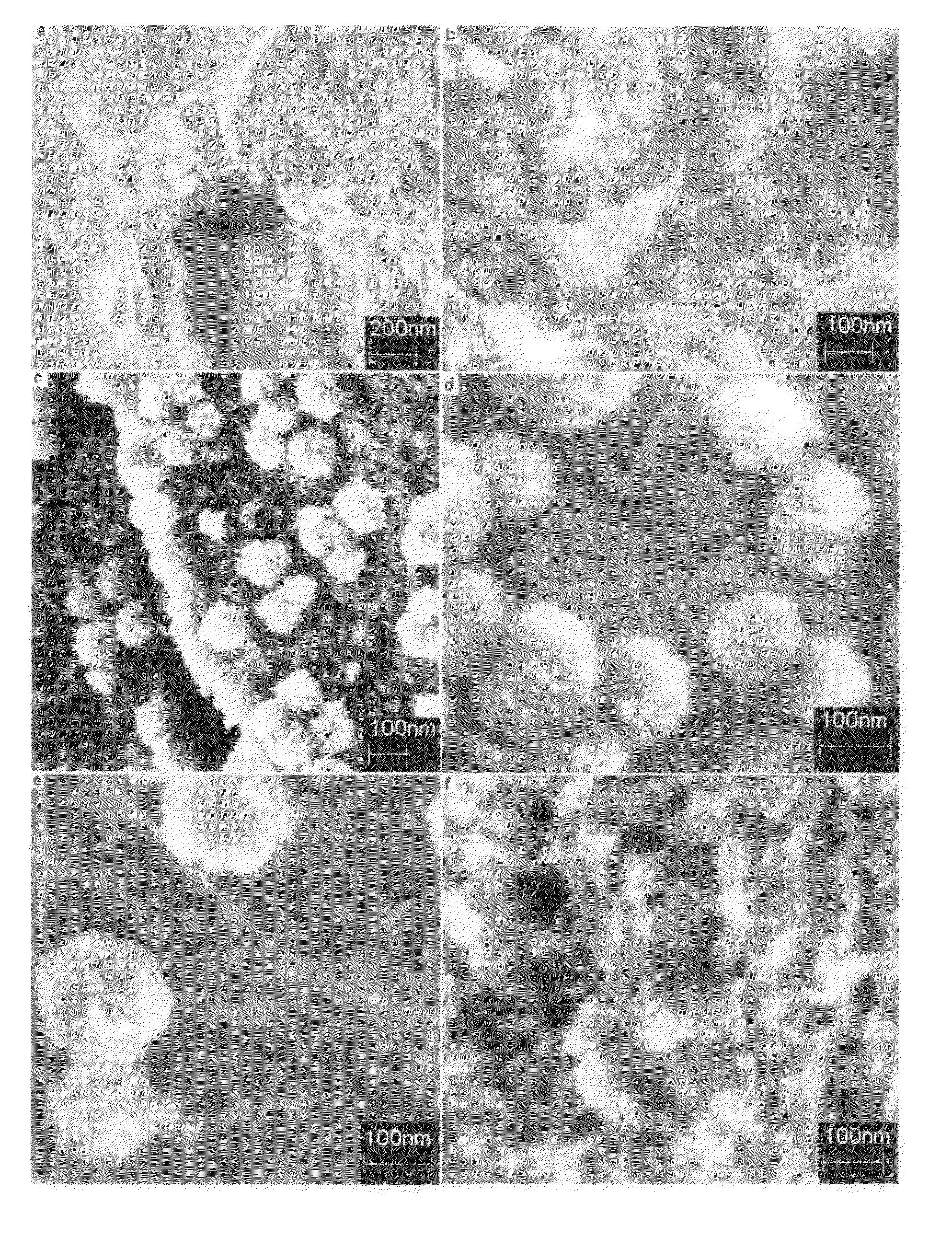
[0058]SWNTs were synthesized in powder form using carbon monoxide (CO) as the carbon source and magnesium oxide (MgO) as the catalyst support material. A detailed parametric study of the various factors influencing the growth of the SWNTs was performed. More particularly, the effects of catalyst type, bimetallic catalyst composition, growth temperature, and flow rate and partial pressure of the carbon source, were investigated. In general, the SWNT growth process consisted of three stages, namely: catalyst / support preparation, catalyst / support calcination and reduction, and finally, SWNT growth followed by purification.

Catalyst Preparation:

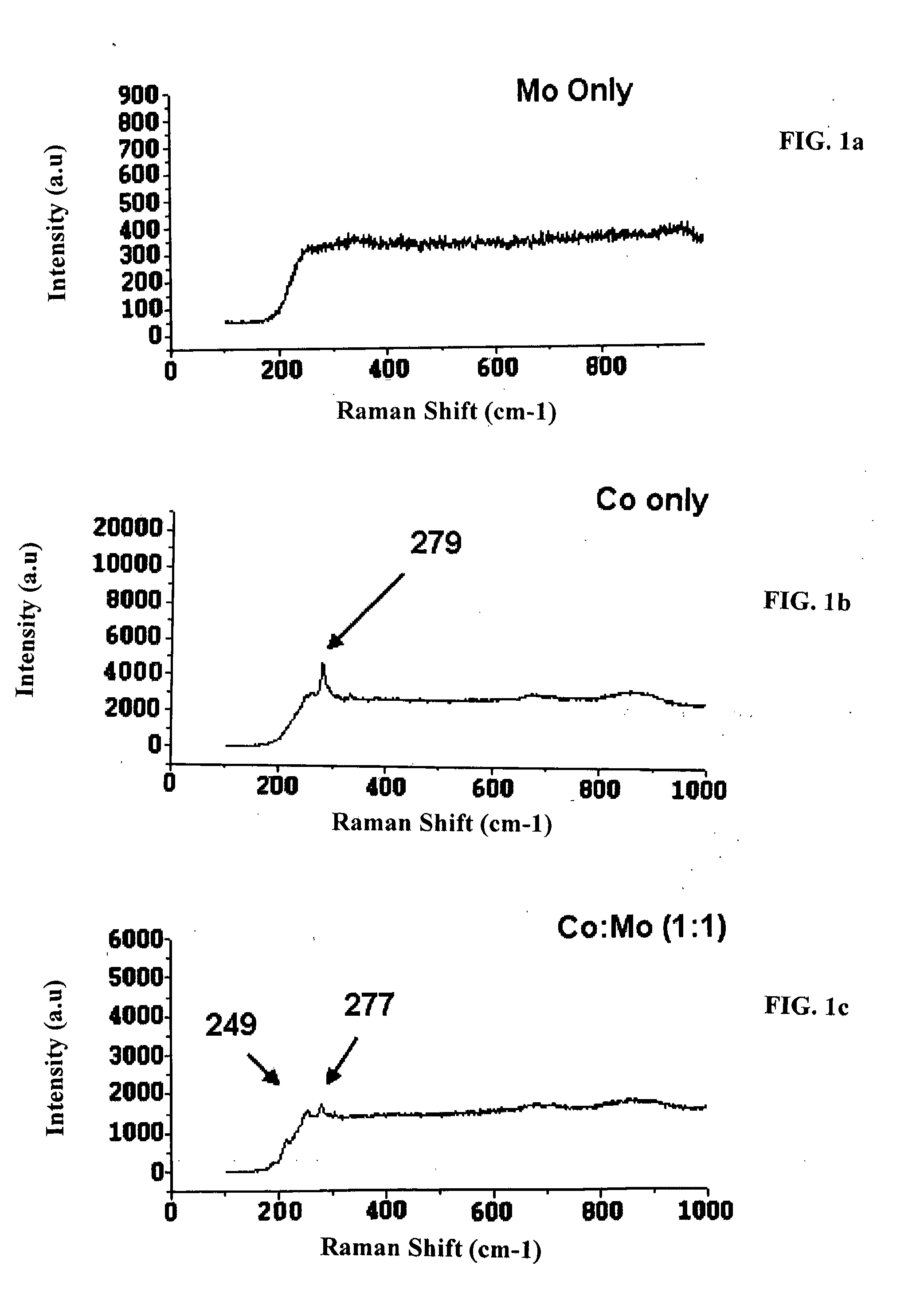
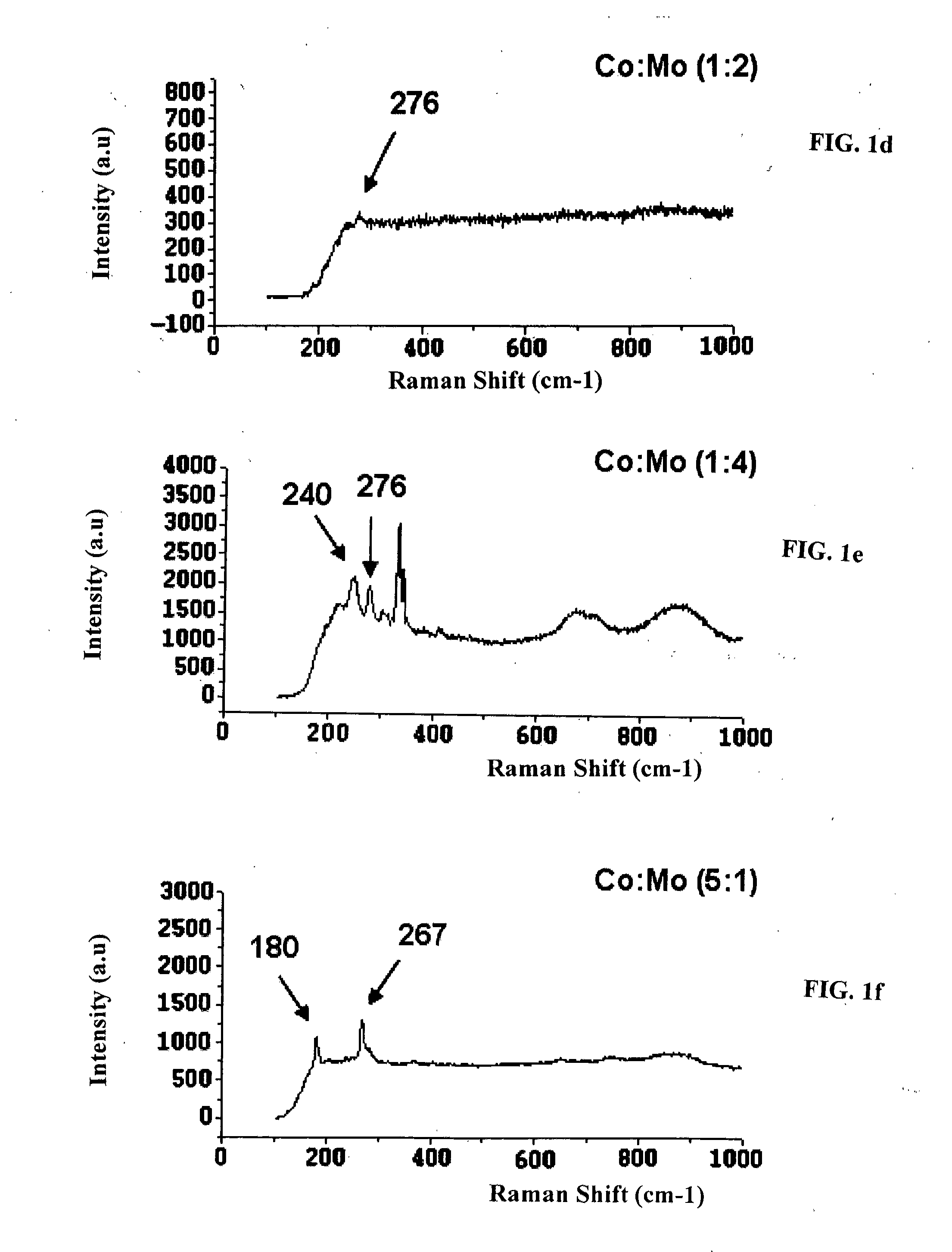
[0059]Sample catalysts / supports were prepared by a wet mixing and combustion synthesis method. Magnesium nitrate hexahydrate [Mg(NO3).6H2O], cobalt nitrate hexahydrate [Co(NO3).6H2O], ammonium heptamolybdate [(NH4)6Mo7O24.4H2O] and citric acid (all from Sigma Aldrich) were mixed with enough distilled water to form a clear solution. Part of the sol...


PUM


Abstract

The present disclosure provides for systems and methods for producing carbon nanotubes. More particularly, the present disclosure provides for improved systems and methods for producing single wall carbon nanotubes (SWNTs) by chemical vapor deposition (CVD) using a carbon source in the presence of a catalyst. In exemplary embodiments, the present disclosure provides for improved systems and methods for producing single wall carbon nanotubes (SWNTs) by chemical vapor deposition (CVD) using carbon monoxide (CO) disproportionation in the presence of a catalyst composition on a catalyst support material. In one embodiment, the present disclosure provides for systems and methods for producing single wall carbon nanotubes (SWNTs) by chemical vapor deposition (CVD) using carbon monoxide (CO) disproportionation with CO pressure from about 0.20 atm to about 1.0 atm in the presence of a cobalt / molybdenum catalyst composition on a magnesium oxide catalyst support.

Description

RELATED FEDERALLY SPONSORED RESEARCH[0001]The work described in this patent disclosure was sponsored by the following Federal Agencies: U.S. Army ARDEC: DAAE30-03-D-1015 and DAAE30-02-C-1139.BACKGROUND[0002]1. Technical Field[0003]The present disclosure relates to systems and methods for producing carbon nanotubes, and, more particularly, to systems and methods for producing single wall carbon nanotubes (SWNTs) by chemical vapor deposition (CVD) using a carbon source in the presence of a catalyst.[0004]2. Background Art[0005]In general, there is a demand for carbon nanotubes in many industries. For example, carbon nanotubes typically possess properties (e.g., thermal, electrical and / or mechanical properties) that are useful in a myriad of different environments for commercial and industrial applications (e.g., electrical applications, semiconductor applications, mechanical applications, structural applications, health and medical applications, etc.). For example, multiwalled carbon ...

Claims


Application Information

Patent Timeline
IPC IPC(8): D01F9/12B82B1/00B82B3/00
CPCC01B31/0233B82Y40/00B82Y30/00C01B2202/02C01B32/162
Inventor GOYAL, AMITZAFAR, IQBAL
Owner NEW JERSEY INSTITUTE OF TECHNOLOGY
Learn More