
System and method for prevention and treatment of peri-implant infection

a technology for peri-implant infection and system and method, applied in the field of system and method for preventing and treating peri-implant infection, can solve the problems of loss of implant, few viable treatment options for this problem, and mediated inflammatory process likely increases the risk of other systemic diseases

Active Publication Date: 2012-06-21
JACOBY BENNETT
View PDF12 Cites 50 Cited by
  • Summary
  • Abstract
  • Description
  • Claims
  • Application Information

AI Technical Summary

Benefits of technology

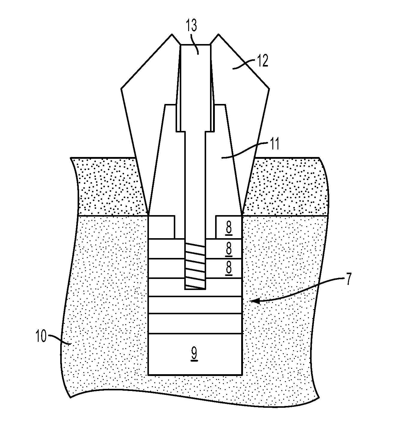
[0012]According to an aspect of the present invention, there is provided a dental implant to be inserted into a jawbone of a patient that includes a base segment provided at one distal end of the implant which is configured to be put inside and come in contact with the jawbone and / or regenerated / graft bone as in the case of bone grafting during a sinus-lift procedure, an attaching portion provided on an opposite end to the one distal end of the implant to which an artificial tooth is configured to be attached, and a plurality of removable segments which are configured to be put inside and come in contact with the jawbone (or regenerated / grafted bone) and are removably attached to the base segment. The segments can also be transgingival only on the coronal end, such that they do not come in contact with the bone. By providing a plurality of removable segments, if peri-implantitis were to occur, these removable segments, if infected, can be removed and either cleaned or replaced to help treat the peri-implantitis.

Problems solved by technology

Over time, the supraosseous implant surface can become colonized with a bacterial biofilm that inflames the gum tissue and often destroys the supporting bone that retains the implant which can result in the loss of the implant.
Few viable treatment options exist for this problem.
This bacterial mediated inflammatory process likely increases the risk for other systemic diseases such as cancer, cardiovascular disease and stroke, as has been shown in periodontitis patients.
Implants can fail or become diseased for several reasons, e.g., due to microorganism colonization of the implant surfaces adjacent to the gingiva and bone, as well as iatrogenic distortion / destruction of the fixture's internal abutment attachment mechanism due to issues such as cross-threading or breakage of the abutment attachment screw.
The inflammation found in both of the above states is associated with increased risk of systemic diseases such as cardiovascular disease, cerebrovascular disease, and cancer.
It is also very difficult to arrest peri-implantitis due to the inability to access and disinfect this rough implant surface.
Surgical success rates in treating peri-implantitis approach 60%, while nonsurgical treatment has been shown to be virtually ineffective.
These low success rates are most likely due to: 1) the exogenous biofilm matrix which protects the bacteria, 2) the fact that the implant surface is such an ideal place for these biofilms to grow, 3) the difficulty of accessing and disinfecting these subgingival surfaces with either surgical or nonsurgical treatment, and 4) the patient's inability or difficulty in maintaining the supragingival surfaces free of bacteria.
While this technique has demonstrated an undocumented 80-90% success rate by eliminating inflammation, it is very costly and time consuming.
In addition, it is not a cure.
Therefore, if the patient's daily oral hygiene is inadequate (due to improper technique or access problems) then the transgingival implant surfaces will recolonize with periodontal pathogens causing recurrence of either peri-implant mucositis or peri-implantitis necessitating retreatment.
With wear and tear, mechanical failure or operator error, these threads can become damaged which may render the implant completely unusable.

Method used


Image

  • System and method for prevention and treatment of peri-implant infection
  • System and method for prevention and treatment of peri-implant infection
  • System and method for prevention and treatment of peri-implant infection

Examples


Embodiment Construction

[0050]The following description of the illustrative, non-limiting embodiments discloses specific configurations, components, and processes. However, the embodiments are merely examples of the present invention, and thus, the specific features described below are merely used to more easily describe such embodiments and to provide an overall understanding of the present invention. Accordingly, one skilled in the art will readily recognize that the present invention is not limited to the specific embodiments described below. Furthermore, the descriptions of various configurations, components, and processes of the embodiments that would have been known to one skilled in the art are omitted for the sake of clarity and brevity.

[0051]A non-limiting embodiment of an implant fixture is shown in FIG. 4. The implant fixture 7 is segmented to include segment sections 8 and a base 9. Also, an abutment 11 is provided on the segments 8 and a final restoration or crown 12 is screwed thereto via scr...


PUM

PropertyMeasurementUnit
lengthaaaaaaaaaa
lengthaaaaaaaaaa
lengthaaaaaaaaaa

Abstract

A system, method and device design to prevent, treat and maintain dental periimplant infections including a dental implant to be inserted into a jawbone of a patient that includes a base segment provided at one distal end of the implant which is configured to be put inside and come in contact with the jawbone, an abutment portion provided on an end opposite to the one distal end of the implant to which an artificial tooth is configured to be attached, and a plurality of removable segments which are configured to be put inside and come in contact with the jawbone and are removably attached to the base segment. If an infection is diagnosed around an implant site, infected removable segments can be extracted while maintaining positioning of the uninfected removable segments and the base segment. The infected removable segments are replaced with cleaned or sterilized removable segments.

Description

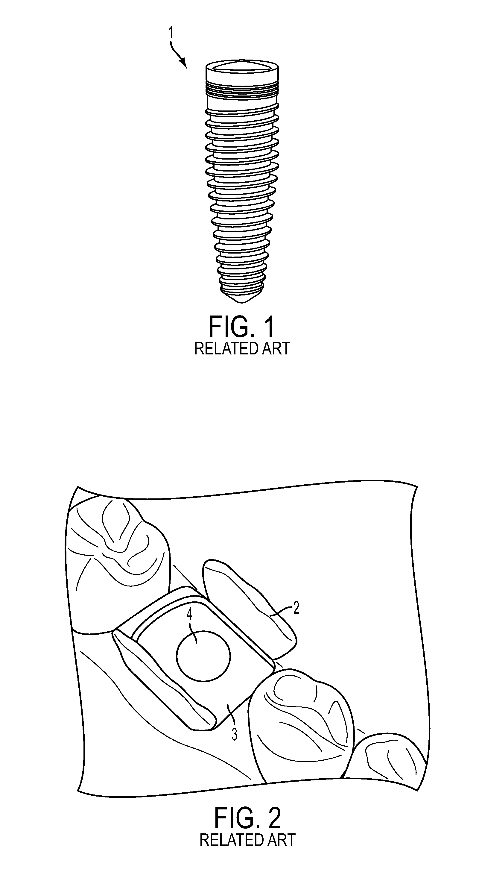
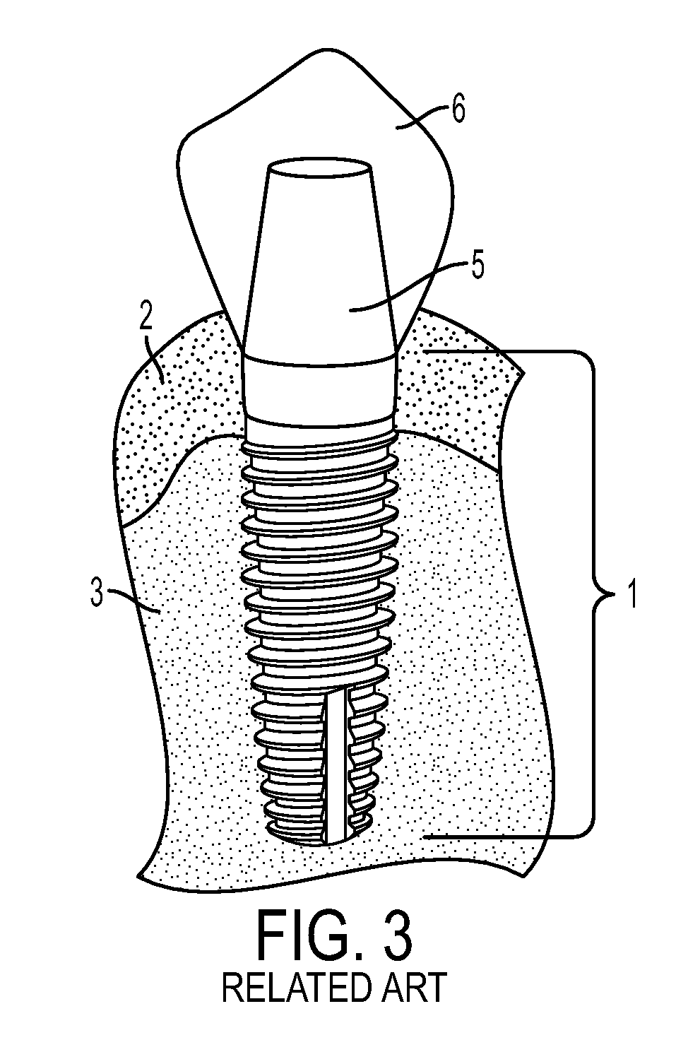
[0001]This application claims the benefit pursuant to 35 U.S.C. §119(e)(1) of U.S. Provisional Application No. 61 / 423455 filed Dec. 15, 2010, the disclosure of which is incorporated herein in its entirety.BACKGROUND OF THE INVENTION[0002]The present invention relates to a system and method for prevention and treatment of peri-implant infection.[0003]Dental implants have become the new standard of care for replacement of missing teeth. As shown in FIG. 1, the dental implants consist of a titanium fixture 1 that may either be threaded or unthreaded on the exterior and usually has a sintered surface. The fixture 1 is placed into the jaw bone surgically by drilling a hole in the bone and screwing or tapping the fixture in, or it is simply screwed into a fresh tooth extraction site. This fixture 1 is then used to retain prosthetic teeth or dentures. Typical dental implant fixture dimensions are 5 mm×10 mm but considerable variation exists. Over time, the supraosseous implant surface can ...

Claims


Application Information

Patent Timeline
Patent Type & Authority Applications(United States)
IPC IPC(8): A61C8/00A61C13/08A61C13/38
CPCA61C8/0062A61C8/0066Y10T29/53A61C13/2656A61C8/0048A61C8/0089Y10T83/849Y10T83/7684
Inventor JACOBY, BENNETT
Owner JACOBY BENNETT
Learn More