Integrated OCT Detector System with Transimpedance Amplifier

Active Publication Date: 2012-07-05
EXCELITAS TECH
View PDF12 Cites 3 Cited by
  • Summary
  • Abstract
  • Description
  • Claims
  • Application Information

AI Technical Summary

Benefits of technology

[0010]The present invention concerns innovations in terms of the integration of the optical interferometer and its detector systems. Embodiments are proposed in which the electronic signal amplifiers, typically transimpedance amplifiers, are closely integrated with the optical detectors that detect the interference signals from the interferometer. Further embodiments are proposed in which the interferometer, but also preferably its detectors, are integrated together on a common optical bench. Systems that have little or no optical fiber can thus be implemented. This yields a highly stable interferometer that is robust against fiber movement, strain and shock. Additionally, the interferometer can be highly compact, enabling lower-cost systems and facilitating the deployment of OCT into new applications that are enabled by such a small size. The inventive OCT optical interferometer and detection systems also have the capability for highly robust optical polarization diversity detection.

Problems solved by technology

Mechanical movement, shock and stress of the optical fiber in these interferometers can affect the propagation of the optical signals in the fiber in terms of optical signal phase and polarization and this can impact system performance of such interferometric optical systems.
For example, increasing the wavelength tuning speed of the swept source, which produces higher OCT image acquisition speeds, also results in greater requirements for the electronics that are used to sample the resulting optical interference signals.

Method used


Image

  • Integrated OCT Detector System with Transimpedance Amplifier
  • Integrated OCT Detector System with Transimpedance Amplifier
  • Integrated OCT Detector System with Transimpedance Amplifier

Examples


second embodiment

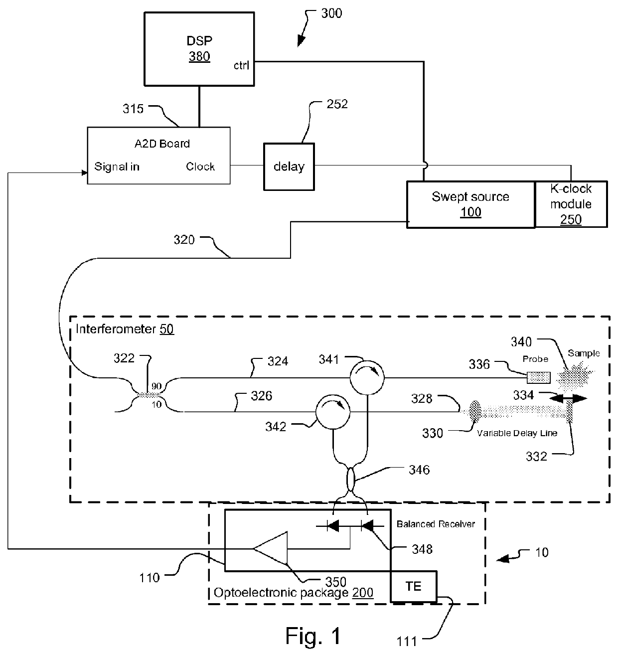
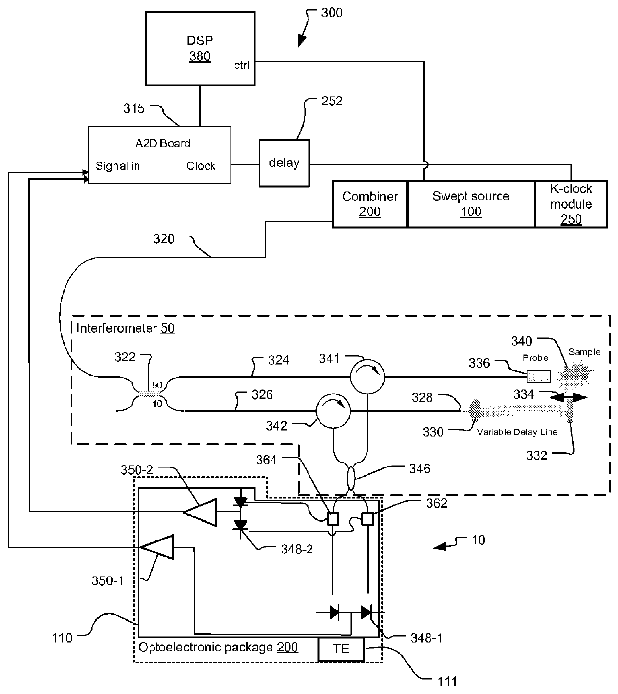
[0044]FIG. 2 shows an optical coherence analysis system 300 that has been constructed according to the present invention.

[0045]The integrated detector system 10 has the capacity to separate the interference signals into portions having different polarizations. Specifically, a first polarization beam splitter 362 and a second polarization beam splitter 364 are used to separate the orthogonal polarization components of the interference signals generated by coupler 346.

[0046]Two balanced detectors 348-1 and 348-2 are used to separately detect the interference signals of the two polarizations. Their outputs are amplified by respective transimpedance amplifiers 350-1, 350-2.

[0047]Here also, the two balanced detectors 348-1 and 348-2 along with the transimpedance amplifiers 350-1, 350-2 are integrated together on a common optical bench 110, along with other optical components such as the first polarization beam splitter 362 and a second polarization beam splitter 364. This bench 110 is fu...

third embodiment

[0049]FIG. 3 shows an optical coherence analysis system 300 that has been constructed according to the present invention.

[0050]This third embodiment includes the capability to perform spectroscopic or other optical analysis on the sample 340.

[0051]In more detail, in the preferred embodiment, two optical fibers are provided to the probe 336. Optical fiber 350 transmits combined signal including first tunable optical signal generated by a first swept source 100-1 and the second tunable optical signal generated by a second swept source 100-2 to the probe 336, which directs the signals to the sample 340. Light returning from the sample 340 that is used for optical coherence analysis returns on optical fiber 350 to circulator 341. This returning light is processed as described in the previous embodiments to generate an optical coherence analysis of the sample 340.

[0052]In contrast, light that is used for spectral analysis of the sample 340 is coupled from the probe on optical fiber 352. ...


PUM


Abstract

An optical detector system comprises a hermetic optoelectronic package, an optical bench installed within the optoelectronic package, a balanced detector system installed on the optical bench. The balanced detector system includes at least two optical detectors that receive interference signals. An electronic amplifier system installed within the optoelectronic package amplifies an output of at least two optical detectors. Also disclosed is an integrated optical coherence tomography system. Embodiments are provided in which the amplifiers, typically transimpedance amplifiers, are closely integrated with the optical detectors that detect the interference signals from the interferometer. Further embodiments are provided in which the interferometer but also preferably its detectors are integrated together on a common optical bench. Systems that have little or no optical fiber can thus be implemented.

Description

RELATED APPLICATIONS[0001]This is application is related to U.S. patent application Ser. No. [Attorney Docket No. 0005.1181U52], filed on an even date herewith, entitled “Integrated Optical Coherence Tomography System” by Inventor Dale C. Flanders, which is incorporated herein by reference in its entirety.BACKGROUND OF THE INVENTION[0002]Optical coherence analysis relies on the use of the interference phenomena between a reference wave and an experimental sample wave or between two parts of a sample wave to measure distances and thicknesses, and calculate indices of refraction of a sample. Optical Coherence Tomography (OCT) is one example technology that is used to perform usually high-resolution cross sectional imaging. It is often applied to imaging biological tissue structures, for example, on microscopic scales in real time. Optical waves are reflected from an object or sample and a computer produces images of in depth cross sections of the object by using information on how the...

Claims


Application Information

Patent Timeline
IPC IPC(8): G02B27/42
CPCG01B9/02004G01B9/0203G01B9/02051G01B9/02069G01B9/02091G01B2290/70
Inventor FLANDERS, DALE C.MURDZA, RANDAL A.
Owner EXCELITAS TECH
Why Eureka
Try Eureka