Al technical title is built by PatSnap Al team. It summarizes the technical point description of the patent document.
a magnetic field sensor and micro-machine technology, applied in the field of sensors, can solve the problems of limiting the minimum detectable signal level, offset variation, and high consumption of a close-loop control system that is complicated and could consume as high as 1 milliwatt per axis
Active Publication Date: 2012-07-12
INVENSENSE
View PDF21 Cites 22 Cited by
Summary
Abstract
Description
Claims
Application Information
AI Technical Summary
This helps you quickly interpret patents by identifying the three key elements:
Problems solved by technology
Method used
Benefits of technology
[0015]In designing high sensitivity, high manufacturability, low cost, and low power consumption Lorentz force magnetic field sensors, the present invention addresses the need of:
[0016]1. High-manufacturability, low power consumption, and low Brownian noise by establishing a open-loop dual-mode resonating devices;
[0017]2. High sensitivity and low cost fabrication by deploying electrostatic coupling spring with high bias voltage at the sensing subsystem;
[0019]a) electrical shield structures comprising at least one electrical source connected to at least one electrode to reduce the electrostatic offset force along the second axis generated by parasitic capacitors around the drive subsystem;
[0021]c) the voltage of the electrical source of the shield structures is equal to the voltage of the drive point of the drive subsystem to minimize the electrostatic offset force.
Problems solved by technology
In prior art, a close-loop frequency control system is needed to adjust the driving frequency dynamically to prevent significant sensitivity variation and the complicated close-loop control system could consume as high as 1 milliwatt per axis.
In addition, the offset is generally larger than the signal and the offset variation limits the minimum detectable signal level.
Thus, the design to mitigate offset is critical.
Method used
Image
Click on the blue label to locate the original text in one second.
Reading with bidirectional positioning of images and text.
Examples
Embodiment Construction
[0043]The present invention relates generally to sensors and more particularly to micromachined resonant magnetic field sensors. The following description is presented to enable one of ordinary skill in the art to make and use the invention and is provided in the context of a patent application and its requirements. The present invention is not intended to be limited to the implementations shown but is to be accorded the widest scope consistent with the principles and features described herein.
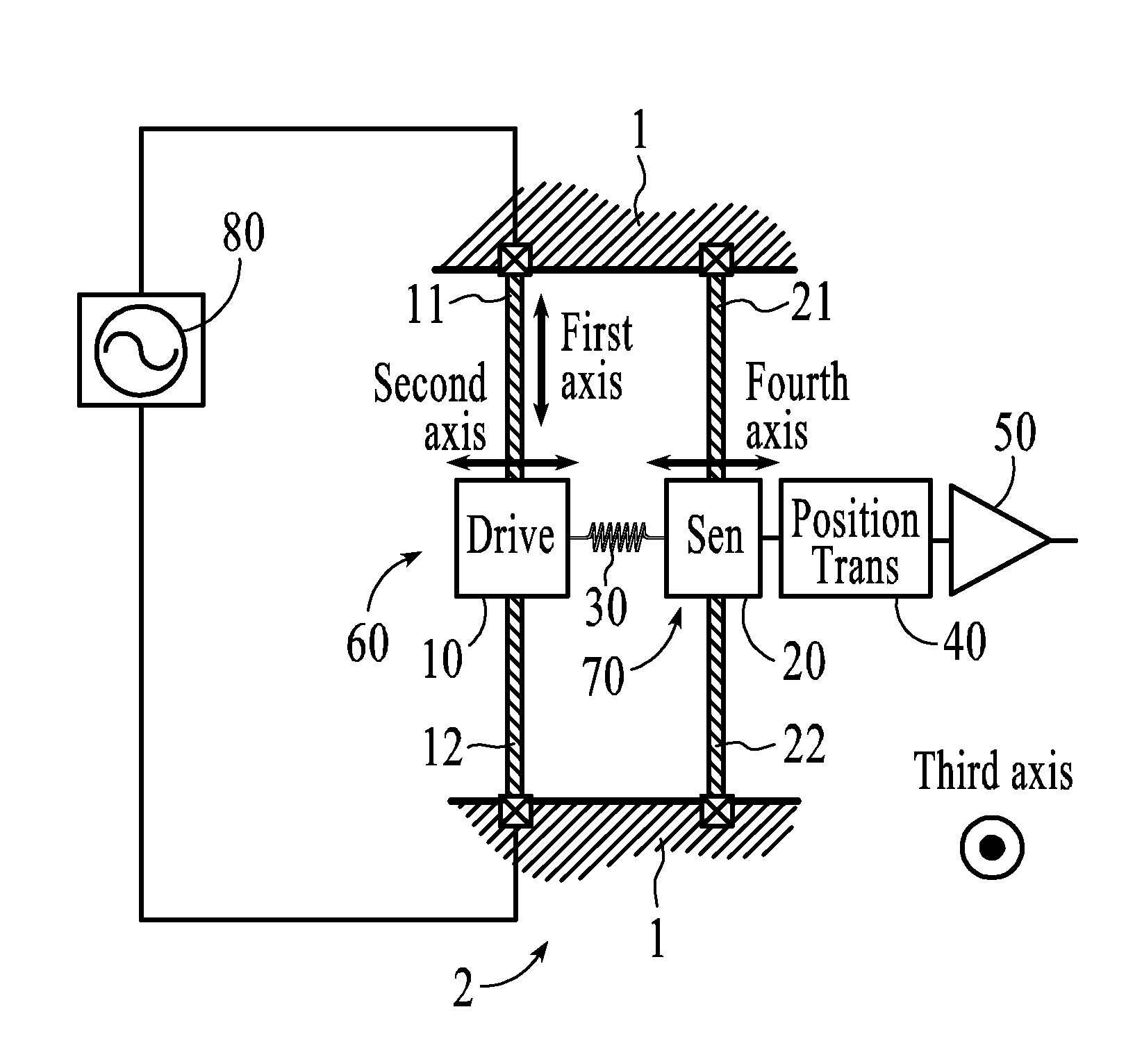
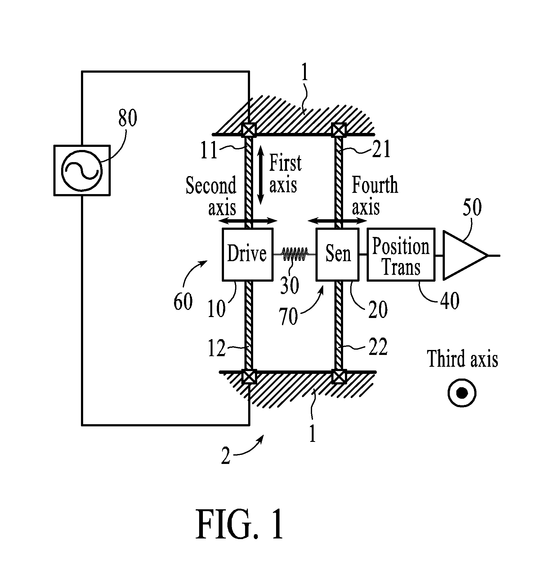
[0044]An embodiment of an open-loop Lorentz-force magnetic sensing device is shown in FIG. 1.
System
[0045]The dual mode open-loop system 2 comprises a drive subsystem 60, a sense subsystem 70 and a coupling spring 30, a position transducer 40, signal processing electronics 50, and drive electronics 80 for supplying a current flowing through a portion of the drive subsystem 60. The drive subsystem 60 comprises a plurality of beams, such that in the presence of a magnetic field, the drive subsyst...
PUM
Abstract
A micromachined magnetic field sensor comprising is disclosed. The micromachined magnetic field comprises a substrate; a drive subsystem, the drive subsystem comprises a plurality of beams, and at least one anchor connected to the substrate; a mechanism for providing an electrical current through the drive subsystem along a first axis; and Lorentz force acting on the drive subsystem along a second axis in response to a magnetic field along a third axis. The micromachined magnetic field sensor also includes a sense subsystem, the sense subsystem comprises a plurality of beams, and at least one anchor connected to the substrate; wherein a portion of the sense subsystem moves along a fourth axis; a coupling spring between the drive subsystem and the sense subsystem which causes motion of the sense subsystem in response to the magnetic field; and a position transducer to detect the motion of the sense subsystem.
Description
RELATED APPLICATIONS[0001]U.S. Pat. No. 6,892,575, entitled “X-Y Axis Dual-Mass Tuning Fork Gyroscope with Vertically Integrated Electronics and Wafer-Scale Hermetic Packaging,” issued May 17, 2005,[0002]U.S. Pat. No. 6,939,473, entitled “Method of Making an X-Y Axis Dual-Mass Tuning Fork Gyroscope with Vertically Integrated Electronics and Wafer-Scale Hermetic Packaging,” issued Sep. 6, 2005,[0003]U.S. Pat. No. 7,104,129, entitled “Vertically Integrated MEMS Structure,” issued Sep. 12, 2006,[0004]U.S. Pat. No. 7,247,246, entitled “Vertical Integration of a MEMS Structure with Electronics in a Hermetically Sealed Cavity,” issued Jul. 24, 2007.[0005]U.S. Pat. No. 7,442,570, entitled “Method of Fabrication of Al / GE Bonding in a Wafer Packaging Environment and a Product Produced Therefrom,” issued Oct. 28, 2008,[0006]U.S. patent application, Ser. No. 12 / 184,231, entitled “Method of Fabrication of Al / GE Bonding in a Wafer Packaging Environment and a Product Produced Thereupon,” filed on...
Claims
Application Information
Patent Timeline
Application Date:The date an application was filed.
Publication Date:The date a patent or application was officially published.
First Publication Date:The earliest publication date of a patent with the same application number.
Issue Date:Publication date of the patent grant document.
PCT Entry Date:The Entry date of PCT National Phase.
Estimated Expiry Date:The statutory expiry date of a patent right according to the Patent Law, and it is the longest term of protection that the patent right can achieve without the termination of the patent right due to other reasons(Term extension factor has been taken into account ).
Invalid Date:Actual expiry date is based on effective date or publication date of legal transaction data of invalid patent.
Patent Type & Authority Applications(United States)