Methods and apparatus for an adjustable stiffness catheter

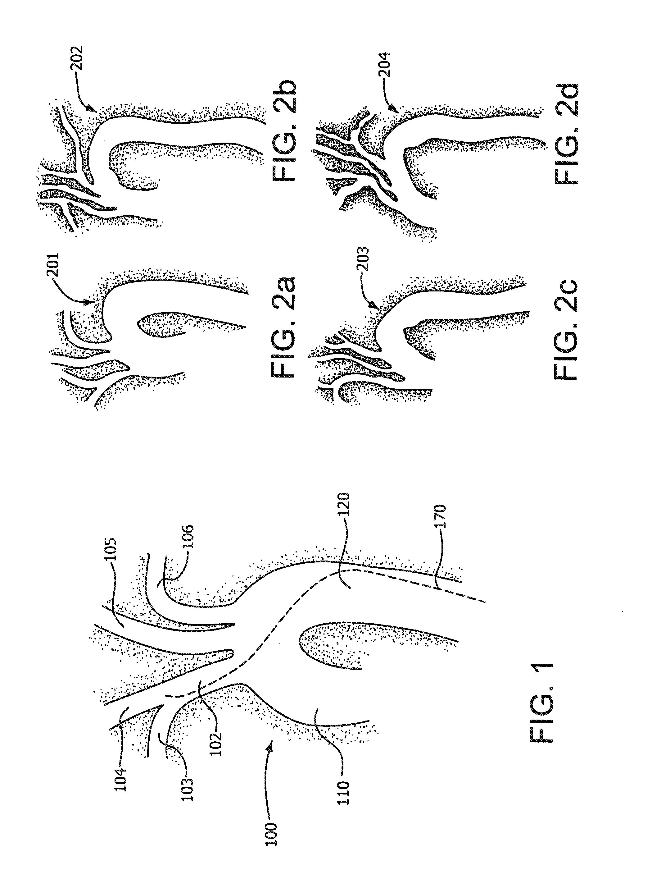
a catheter and adjustable technology, applied in the field of catheter systems, can solve the problems of difficult selective catheterization of certain vessels of the human body, navigation from the descending aorta, aorta, etc., and achieve the effect of easy navigation of the guide wir

Inactive Publication Date: 2012-07-12
WL GORE & ASSOC INC
View PDF3 Cites 32 Cited by
  • Summary
  • Abstract
  • Description
  • Claims
  • Application Information

AI Technical Summary

Benefits of technology

[0008]The present invention generally relates to a catheter assembly having an adjustable stiffness during, for example, endovascular procedures within the human body. That is, the stiffness or a comparable mechanical characteristic of the catheter assembly may be adjuste...

Problems solved by technology

It is often difficult, however, to selectively catheterize certain vessels of the human body due to the tortuous paths that the vessels follow. FIG. 1, for example, is a conceptual diagram useful in depicting the human aortic arch 100.
It is clear that navigation from the descending aorta 120, up over the arch, and then back to gain access to the right brachiocepalic artery 102 can ...

Method used


Image

  • Methods and apparatus for an adjustable stiffness catheter
  • Methods and apparatus for an adjustable stiffness catheter
  • Methods and apparatus for an adjustable stiffness catheter

Examples


embodiment 1

Thermal Activation

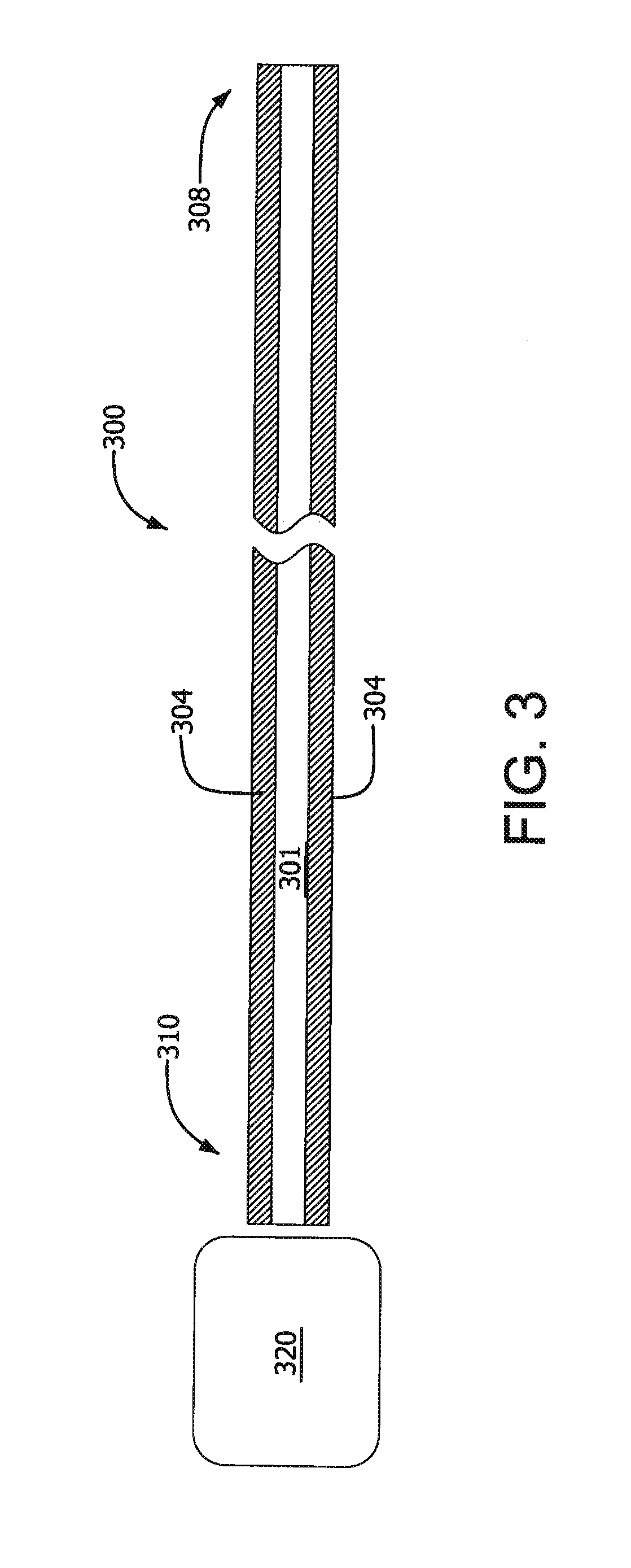
[0039]In one embodiment, the activation means includes a controller 320 communicatively coupled to body 304 as well features within body 304 that are together adapted to place the body in the second state by subjecting at least a portion of the catheter 300 to a reduction or change in temperature.

[0040]Referring now to FIGS. 8 (a)-(b) in conjunction with FIG. 1, a catheter 300 in accordance with one embodiment generally includes two auxiliary lumens or channels 802 and 804 that are interconnected (e.g., fluidly coupled near a distal end) such that the coolant travels through body 304. The channels 804 and 802 are separated, for example, by a membrane (such as an ePTFE membrane) 806.

[0041]After delivery of catheter 300 (during which it is in the first state), a coolant 805 such as liquid nitrogen is supplied to channel 804 (e.g., via a coolant delivery system within controller 320), where it travels parallel to lumen 301 along the length of (or a portion of) body 30...

embodiment 2

Axial Compression

[0043]Referring now to FIGS. 16 and 17 in conjunction with FIG. 1, in one embodiment, the activation means includes controller 320 communicatively coupled to the body 304 and components within body 304 that are adapted to place body 304 in the second state by subjecting it to an increase in axial compression.

[0044]As shown in FIG. 16, one or more tension lines 1602 may be used to selectively apply a compressive force to body 304. The tension lines 1602 are attached at the distal end 308 of catheter 300 and are slideably received by corresponding accessory lumens 1402 that pass through a series of body segments 1605. The accessory lumens 1402 are preferably sized to allow the free axial movement of tension lines 1602. Depending upon the particular design, body segments 1605 will typically be separated by a small interstitial gaps 1607.

[0045]The tension lines 1602 are subjected to approximately zero tension (i.e., are generally “slack”) while navigating the anatomy du...

embodiment 3

Radial Compression

[0049]In one embodiment, the activation means includes controller 320 communicatively coupled to the body 304 and adapted to place the body 304 in the second state by subjecting at least a portion of the tubular body to an increase in radial compression. For example, body 304 may include two fluid impermeable layers defining a pressure-responsive chamber and at least one interstitial structure provided within the pressure-responsive chamber. The controller is configured to cause a change in internal pressure within the pressure-responsive chamber; and the interstitial structure is adapted to exhibit radial compression in response to the change in internal pressure.

[0050]Referring now to FIG. 9, in the illustrated embodiment catheter 300 includes an accessory lumen 902 extending from chambers 906 to a hub 302. Hub 302 in this embodiment is configured as a standard “Y” fitting, wherein negative pressure (i.e., a reduction from some baseline pressure) is applied be at...


PUM

PropertyMeasurementUnit
Temperatureaaaaaaaaaa
Structureaaaaaaaaaa
Responsivityaaaaaaaaaa

Abstract

Apparatus and methods for an endovascular catheter that can be inserted within tortuous body anatomies and then selectively stiffened and fixed in place. In a particular embodiment, this stiffness is reversible. The stiffness or a comparable mechanical characteristic of the catheter assembly may be adjusted to a relatively low value during insertion (so that it easily navigates a guide wire or the like), and then subsequently adjusted to a relatively high value in situ to keep the catheter assembly substantially fixed in place (i.e., during delivery of an interventional device).

Description

CROSS-REFERENCE TO A RELATED APPLICATION[0001]This application claims the priority benefit under 35 U.S.C. §119(e) of U.S. Provisional Application No. 61 / 430,303 filed on Jan. 6, 2011, the content of which is incorporated herein in its entirety.TECHNICAL FIELD[0002]Embodiments of the subject matter described herein generally relate to catheter systems, and more particularly relate to catheters of the type used in the context of tortuous anatomic features.BACKGROUND[0003]Catheters are useful in performing a wide range of medical procedures, such as diagnostic heart catheterization, percutaneous transluminal coronary angioplasty, and various endocardial mapping and ablation procedures. It is often difficult, however, to selectively catheterize certain vessels of the human body due to the tortuous paths that the vessels follow. FIG. 1, for example, is a conceptual diagram useful in depicting the human aortic arch 100. As shown, the ascending aorta 110 rises from its origin at the aorti...

Claims


Application Information

Patent Timeline
IPC IPC(8): A61M25/092A61M25/00
CPCA61M25/0045A61M25/0051A61M25/0054A61M25/0053A61M2025/0064A61M2205/0266A61M25/0102A61M25/0012A61M25/005A61M2025/0025
Inventor CULLY, EDWARD H.DUNCAN, JEFFREY B.TRAPP, BENJAMIN M.
Owner WL GORE & ASSOC INC
Why Eureka
Try Eureka