Memory control circuit and integrated circuit including branch instruction and detection and operation mode control of a memory

a memory control circuit and integrated circuit technology, applied in the field of memory control, can solve the problems of reducing the power consumption of the microcomputer as a whole, increasing the size of the memory used in the microcomputer, and preventing the degradation of processing efficiency in the microcomputer, so as to reduce the power consumption of the memory and prevent the degradation of the processing efficiency of the microcomputer

Active Publication Date: 2012-07-12
RENESAS ELECTRONICS CORP
View PDF0 Cites 4 Cited by
  • Summary
  • Abstract
  • Description
  • Claims
  • Application Information

AI Technical Summary

Benefits of technology

[0012]The present inventors, however, have found the following problems. Although the technique disclosed in Japanese Unexamined Patent Application Publication No. 2007-193433 reduces power consumption by lowering the execution frequency of operation processing with use of the penalty that occurs at the time of cache replacement, the effect of reducing the power consumption of the microcomputer as a whole would be limited unless the power consumption of the memory itself is reduced.
[0019]According to the technique of the present invention, it is possible to reduce the power consumption of a memory and prevent the degradation of processing efficiency in a microcomputer.

Problems solved by technology

Accordingly, the size of a memory used in the microcomputer significantly increases, so that the power consumption of the memory forms an increasingly large proportion in the microcomputer.
Although the technique disclosed in Japanese Unexamined Patent Application Publication No. 2007-193433 reduces power consumption by lowering the execution frequency of operation processing with use of the penalty that occurs at the time of cache replacement, the effect of reducing the power consumption of the microcomputer as a whole would be limited unless the power consumption of the memory itself is reduced.
Because the starting time is longer than a memory read access time, a waiting time occurs in memory access until the mode change is completed, which degrades the system processing performance.

Method used


Image

  • Memory control circuit and integrated circuit including branch instruction and detection and operation mode control of a memory
  • Memory control circuit and integrated circuit including branch instruction and detection and operation mode control of a memory
  • Memory control circuit and integrated circuit including branch instruction and detection and operation mode control of a memory

Examples


first exemplary embodiment

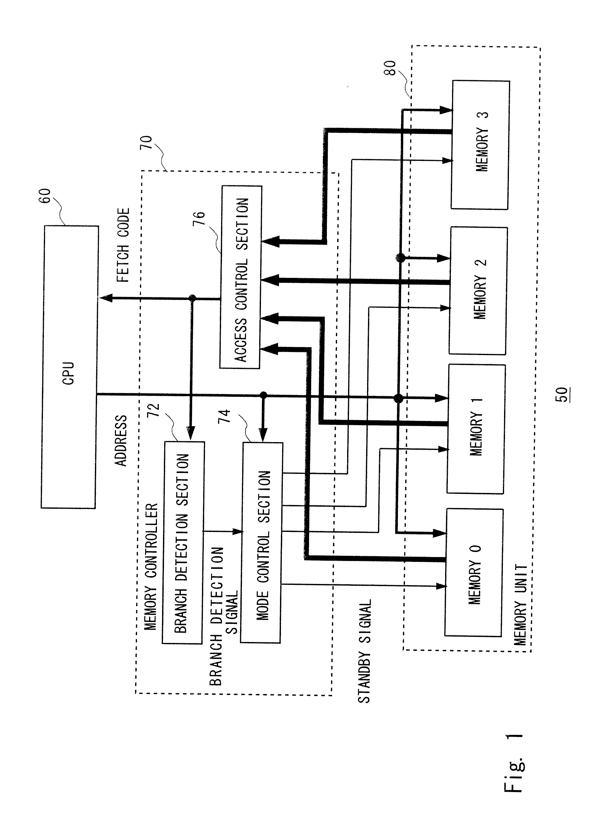
[0056]FIG. 3 shows a microcomputer 100 according to a first exemplary embodiment of the present invention. The microcomputer 100 includes a CPU 101, a cache memory 102, and a plurality of main memories (main memories 107 to 110). The CPU 101 is connected to the cache memory 102 and each main memory via a fetch address control circuit 103, a fetch code control circuit 104, a data selector 105 and a memory control circuit 200.

[0057]The cache memory 102 is a general cache memory. The main memories 107 to 110 have a normal mode and a standby mode that consumes lower power than the normal mode, and it is set to either mode by the memory control circuit 200. In this exemplary embodiment, a circuit through which current constantly flows in the main memory is suspended as an example of the standby mode. When returning from the standby mode to the normal mode, a time to resume the operation of the suspended circuit in the main memory is generally longer than a read cycle. For example, it is ...

second exemplary embodiment

[0134]An integrated circuit 500 shown in FIG. 8 corresponds to the memory control circuit 200 and each main memory in the microcomputer 100 shown in FIG. 3. The microcomputer to which such an integrated circuit is applied is described hereinafter as a second exemplary embodiment of the present invention. To avoid redundant explanation, the description and illustration of the elements other than the integrated circuit 500 are not provided below. In FIG. 8, the elements having the same configuration or function as those in the memory control circuit 200 shown in FIG. 4 are denoted by the same reference symbols.

[0135]A standby mode selection signal 509 for a selection among a plurality of standby modes is connected to main memories 501 to 504 shown in FIG. 8. A branch preparation control circuit 513 is configured by adding an adder 505 and a selector 506 to the branch preparation control circuit 113 of the memory control circuit 200. The selector 506 selects either output of the adder ...


PUM


Abstract

A memory control circuit includes a branch detection section to detect a branch instruction from an instruction fetched from a memory unit including a plurality of operation modes, and a mode control section to change an operation mode of the memory unit according to a detection result by the branch detection section. The memory unit includes a plurality of memories, the plurality of operation modes include a normal mode allowing access and a standby mode consuming a lower power than the normal mode, and in response to the detection of a branch instruction from an instruction fetched from any one of the plurality of memories, the mode control section makes standby release of the other memories.

Description

[0001]The present application is a Continuation application of U.S. patent application Ser. No. 12 / 318,211 filed on Dec. 23, 2008, which is based on Japanese Patent Application No. 2008-174635, filed on Jul. 3, 2008, the entire contents of which is incorporated herein by referenceBACKGROUND[0002]1. Field of the Invention[0003]The present invention relates to memory control and, particularly, to a memory control technique in a microcomputer.[0004]2. Description of Related Art[0005]Lower current consumption of electronic equipment is strongly demanded today for environmental consciousness and so on, and an attempt has been made to reduce the current consumption of a microcomputer incorporated in electronic equipment.[0006]A technique disclosed in Japanese Unexamined Patent Application Publication No. 2007-193433 is described hereinafter with reference to FIG. 9. FIG. 9 corresponds to FIG. 1 of Japanese Unexamined Patent Application Publication No. 2007-193433. In a processor shown the...

Claims


Application Information

Patent Timeline
Patent Type & Authority Applications(United States)
IPC IPC(8): G06F1/00
CPCG06F1/3203G06F1/3275G06F9/3804Y02B60/1228G06F2212/6028Y02B60/1225Y02B60/32G06F12/0862Y02D10/00Y02D30/50
Inventor YAMAZOE, KIMINARI
Owner RENESAS ELECTRONICS CORP
Why Eureka
Try Eureka