Heat conveying structure for electronic device

a technology of conveying structure and electronic device, which is applied in the direction of cooling/ventilation/heating modification, semiconductor devices, basic electric elements, etc., can solve the problems of large area ratio of hoard for connecting between respective devices, inability to mount high-level heat sinks immediately above lsi or ic, and inability to reduce the driving power and noise of fans, increase the heat transfer amount, and reduce the effect of thermal resistan

Active Publication Date: 2012-07-19
NEC CORP
View PDF12 Cites 22 Cited by
  • Summary
  • Abstract
  • Description
  • Claims
  • Application Information

AI Technical Summary

Benefits of technology

[0022]According to the heat conveying structure for an electronic device of the present invention, for example, even when an LSI or IC having a large amount of heat generation is mounted on a low electronic device, heat can be transferred to a radiator provided outside the device and cooled. Consequently, a fan or the like need not be rotated more than necessary, and driving power and noise of the fan can be reduced. This is because the evaporating section and the condensing section have the chamber structure with fins erected therein, to cause gas-liquid two-phase flow, thereby increasing the heat transfer amount, and the thermal resistance is reduced due to an increase in the area of the condensing section.
[0023]Moreover, according to the heat conveying structure for an electronic device of the present invention, maintenance and replacement of the electronic device can be facilitated. This is because, by having a structure where a large radiator is not provided on condensing section connected to the LSI or IC, it is thermally connected to the radiator outside of the electronic device, and the condensing section and the radiator can be separated, a large radiator need not pass through a small opening on the electronic device side.

Problems solved by technology

Consequently, a tall heat sink cannot be mounted immediately above the LSI or IC.
However, when the electronic device represented by a 1U server or a blade server is a low type device having a height of about 40 mm or less, an area ratio of a hoard for connecting between respective devices, referred to as a backplane and a middle plane for performing signal transmission or power feeding, which is provided in a direction of wind of the device, becomes relatively large.
Therefore, an opening for sending cool wind into the device, a so-called air hole, is only minimally provided in the electronic device.
Consequently, wind is forcibly fed by a fan having high static pressure in order to circulate wind to a small opening, and hence the driving power and noise of the fan increases more than necessary.

Method used


Image

  • Heat conveying structure for electronic device
  • Heat conveying structure for electronic device
  • Heat conveying structure for electronic device

Examples


first exemplary embodiment

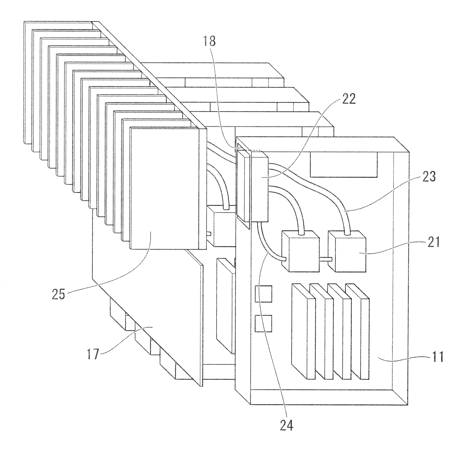
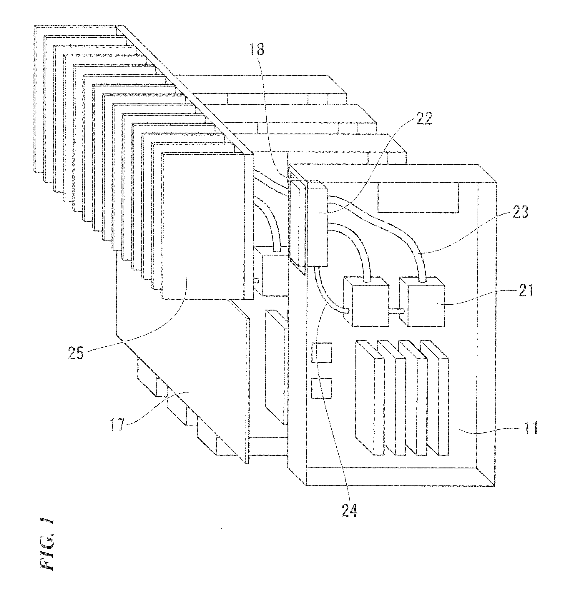
[0034]FIG. 1 is a schematic view of one example of a blade card mounted with a heat conveying structure for an electronic device, according to a first exemplary embodiment of the present invention.

[0035]Functions of the electronic device are combined on one card 11. A plurality of cards 11 are connected to a backplane 17 via a connector or the like. An LSI or IC having a large amount of heat generation such as a CPU is mounted on the card 11. An evaporating section 21 is mounted directly above the LSI. A condensing section 22 is mounted in an opening section 18, which is an empty area, which is not connected to the backplane 17 of the card 11, and is thermally connected to a radiation part 25. The radiation part 25 is thermally connected to the plurality of cards 11 and is intensively cooled by a fan mounted on a rack.

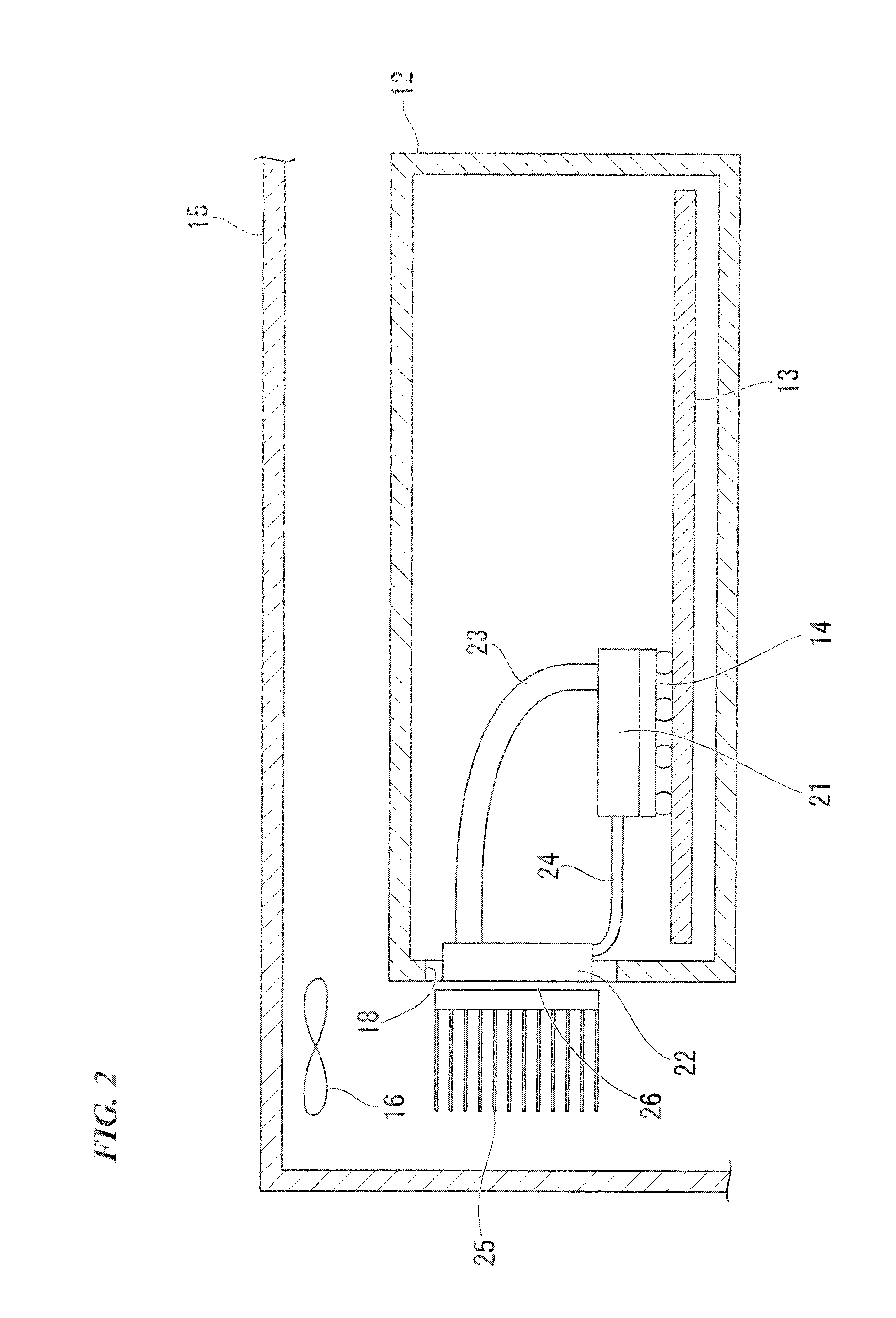
[0036]FIG. 2 shows a cross-sectional view of the heat conveying structure for an electronic device. A plurality of electronic devices 12 mounted with an LSI 14 having ...

second exemplary embodiment

[0053]A second exemplary embodiment of the present invention is shown in FIG. 6.

[0054]A condensing section 22 is thermally connected to a radiator 31 such as a cold plate provided inside of a rack 15, in a state where it is pulled out from an opening section 18 provided in an electronic device 12. The radiator 31 such as a cold plate may liquid cool the condensing section by, for example, providing flow channels therein and flowing liquid such as water in flow channels, or it may air cool the condensing section 22 by a heat sink provided with radiation fins.

[0055]As in the second exemplary embodiment, by providing the condensing section 22 outside of the opening section 18, cold wind can flow into the opening section 18, and for example, a chip set other than a CPU of the electronic device can be cooled. At this time, because the CPU having a large amount of heat generation is separately cooled by the radiator 31 such as the cold plate, driving power of a fan required for cooling in...

third exemplary embodiment

[0056]A third exemplary embodiment of the present invention is shown in FIG. 7.

[0057]An in-side cold water pipe 41 through which cooling water flows into a rack, and an out-side cold water pipe 42 through which cooling water flows out, are provided in a rack 15. A water cooling jacket 43 with flow channels is individually connected to the respective cold ater pipes 41 and 42 by a tube or the like. The water cooling jackets 43 are respectively connected to condensing sections 22 of a plurality of electronic devices 12.

[0058]As in the third exemplary embodiment, by thermally connecting the water cooling jacket 43 to the condensing section 22 one-to-one, it is not required to prepare a radiator in the rack 15 matched with the specification of the electronic device 12 at the time of expansion or maintenance / replacement of the electronic device 12, thereby enabling to simplify the operation.


PUM


Abstract

A heat conveying structure for an electronic device according to the present invention includes: an evaporating section that has a chamber structure with first fins erected therein, is thermally connected to the electronic device, evaporates a liquid coolant on the surfaces of the first fins to thereby change the liquid coolant to a vapor coolant, and sends out liquid coolant present near the first fins along with the vapor coolant as a gas-liquid two-phase flow coolant; a condensing section that has a chamber structure with second fins erected therein, is thermally connected to a radiator provided outside the electronic device, and changes the gas-liquid two-phase flow coolant in contact with the second fins to a liquid coolant; a vapor pipe that connects the evaporating section and the condensing section, and moves the gas-liquid two-phase flow coolant sent out from the evaporating section to the condensing section; and a liquid pipe that connects the evaporating section and the condensing section, and moves the liquid coolant from the condensing section to the evaporating section.

Description

TECHNICAL CAL FIELD[0001]The present invention relates to a heat conveying structure for an electronic device for conveying heat generated from an LSI or IC used for the electronic device to the outside of the electronic device for cooling, when a plurality of electronic devices are mounted on a rack and used.BACKGROUND ART[0002]Recently, electronic devices such as a computer and a network device use a plurality of devices to improve the processing capacity thereof. A method of operating the plurality of devices in parallel to perform distributed information processing or distributed arithmetic operation is mainstream. Since there is a limitation in floor area for installing the electronic device, a method of mounting a plurality of electronic devices on some racks collectively has been adopted. In order to mount as many as possible electronic devices on the rack, the height of each electronic device needs to be lowered. Consequently, a tall heat sink cannot be mounted immediately a...

Claims


Application Information

Patent Timeline
Patent Type & Authority Applications(United States)
IPC IPC(8): F28D15/02
CPCH01L23/427H01L23/473H05K7/20809H01L2924/0002H01L2924/00H05K7/20309H05K7/20318H05K7/20327H05K7/20336H05K7/208
Inventor YOSHIKAWA, MINORU
Owner NEC CORP
Why Eureka
Try Eureka